I was not talking about phases.(Yes, base common is in phase, while emitter common opposite)
Using the traditional emitter common configuration and applying the feedback to the emitter is... a typical current feedback.
Here too, you use the same diode junction to compare the two signals.
BTW: What is the input impedance of your schematic (with incredible bandwidth in regard to the used power devices) ?
Last edited:
The input here is driving base current swings of Q1 Q2 without assistance.
All the other paths are constant current, so its only input providing drive
for the next to final stage of the amplifier. If realizing that fact makes an
input impedance any easier to calculate...
The other parts ARE important as voltage references and amplifiers of
error voltages. But with input into emitters, current gain and input
impedance constancy are not this circuit's strongest selling points.
Plenty old threads about Allison topology cover these issues. This non-
switching scheme is certainly new. I'm not sure if it solves any of the
problems with changes of impedance at crossing aggravating stability?
I've seen stability issues in my sum of Schottkys non-switch scheme.
Its not really a non-switch scheme either. Just moves which transistor
will do AB switching, so switching its not shaped by the biggest slowest
one.
---
Then there's the abstract current sources, or bootstraps, or whatever?
Plenty of opportunity to make a good sim into a real oscillator there...
Last edited:
Interesting twist of reasoning: it is the complete opposite, thus it has to be identical.I was not talking about phases.(Yes, base common is in phase, while emitter common opposite)
Using the traditional emitter common configuration and applying the feedback to the emitter is... a typical current feedback.
Here too, you use the same diode junction to compare the two signals.
Even if you didn't display your country flag, I could have guessed you are a Frenchman
 And perhaps even of Jesuit upbringing.
But in a perverse way, it goes to confirm my own opinions: there is no actual distinction between the two topologies other than artificial ones.
BTW, as soon as feedback exists in a Bjt amplifier, it always boils down to a comparison across B-E: there is no other way to do it, as a transistor only has three nodes, and the collector is normally never used as an input.
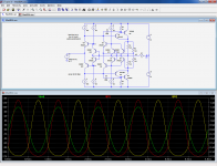
A little more than 50K up to 1KHz and decreasing above due to the capacitive component. See Ken's excellent explanation belowBTW: What is the input impedance of your schematic
That is the small signal bandwidth, the power bandwidth would be more reasonable (but more than enough for audio applications)(with incredible bandwidth in regard to the used power devices) ?
Stability is certainly a touchy issue: I have already melted impressive quantities of silicon trying to grapple with it (Esperado, do you understand why I limit myself to 3055's?I've seen stability issues in my sum of Schottkys non-switch scheme.
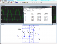
)That is not quite true: the "handover" parameters can be shaped to any degree by altering the current densities ratios in the control transistors. See a "softer" example:Its not really a non-switch scheme either. Just moves which transistor
will do AB switching, so switching its not shaped by the biggest slowest
one.
Attachments
No, i don't see. There is decades since i have not melted any silicon for other reason than big cabling error and no more burned expensive power device. While i don't see how 3055 would keep-you away from oscillating problems. It just add a very low frequency pole where you don't want.S I have already melted impressive quantities of silicon trying to grapple with it (Esperado, do you understand why I limit myself to 3055's?
You don't take enough precautions at first power-on before derating?
BTW: About Jesuits, i wonder where had-you done your studies...may-be a track ?
No idea of configurations where the signal and the feedback are subtracted across resistances ?
You don't like current feedback (i wonder why), that is your problem.
My position is just based on my experience: It is the simplest way i know to achieve DC coupled stable amps with high slew-rates, low TIM and transparent sound that i know.
I never said it was the only one.
Listen, each time i have compared opamps for mixing desks or preamps -so many times and lot of them- the current feedback op amps were clear winners.
And all the best sounding power amps ( > 49W) i have crossed in my life where current feedback too.
The difference can be subtle, but there is one, even if i'm not able to explain why, apart slew rate differences and this important one: NO active device in the feedback-path (adding distortion and delay) .
One exception is Inverting amps, where feedback is applied before input. If TIM of the same order and slew-rate near the same, i feel no big sounding differences.
One of the other "secret" i know for good sounding amps is the bandwidth has to remain near unchanged whatever the signal level. And, of course, NO electrolytic caps in output lines.
Now, i'm sure that i have explored less exotic configurations than -you, and i am very seriously interested by your experiences and opinions about them.
Of course if you correlate with listening comments, measurements are not everything ...
It would be more interesting than arguing on something we agree: Yes there is many solutions to reach our goals, and CFA is one of them.
By simple curiosity, what is the slew rate of your last schematic, and, for the reader, power and gain ?
Last edited:
Interesting twist of reasoning: it is the complete opposite, thus it has to be identical.
... , and the collector is normally never used as an input.
CFB from collector makes this splitter have equal impedance and gain.
*** OK, half each behavior is impedance, and half cross coupled noise
that (if the loads are equal) just happens to look like impedance ***
For those confused by simultaneous CFB from the anode, its the same
theory of operation as the triode hybrid splitter from a few posts back.
We just make a real simple triode emulator using collector as an input.
I remind that it is not normal for the concertina style splitter to have
any voltage gain. But thanks to R3 R4 CFB, this one does. Also is not
normal for top and bottom impedances to be equal. But again, thanks
to R1 R2 and CFB...
Emitter of Q2 swings 1/2 the input voltage, just as it might in a LTP.
Thats probably an important observation, not quite sure why...
Now, look back to Elvee's OP circuit and compare.
Attachments
Last edited:
Thats probably an important observation, not quite sure why...
You missed my point.No, i don't see. There is decades since i have not melted any silicon for other reason than big cabling error and no more burned expensive power device. While i don't see how 3055 would keep-you away from oscillating problems. It just add a very low frequency pole where you don't want.
You don't take enough precautions at first power-on before derating?
The MaxB topology is completely experimental, and it has some interesting peculiarities. Among them, is the independent control of the two bases of OP transistors (required to achieve the linearity).
In more classical topologies, the interbase potential is set rather rigidly by a low impedance network, like a diode string or equivalent.
In MaxB, both bases see a high impedance, from the drive transistor's collectors and the positive and negative CCS. As this wasn't enough, the CCS's pull in opposite directions.
This means that there is not only plenty of room for things to go wrong, but when they do, to do it utterly and in the most spectacular manner.
If there is hiccup in the control part, or a beginning of "vertical" oscillation, it ends in an immediate destruction of the transistors.
Imagine what happens when the vertical loop (the one controlling the xover) oscillates: if the input is fixed at 0 potential, the collectors of the input transistors have a dynamic of ~0 to +/-40V. If the average level establishes itself at 20V, that is sufficient to vaporize instantly the OP transistors.
This can happen for various reasons, inherent stability problems, tests on reactive loads, lock-up of the control part, etc.
I have tried to include to safety accessories, like a diode string supposed to keep things at a safe level when things get out of control, but a string short enough to be effective also tends to disrupt the operation of the circuit and kills the performances.
In the end, I prefer to blow cheap devices until the thing is sufficiently debugged
The result of the subtraction always has to be processed by an active device.No idea of configurations where the signal and the feedback are subtracted across resistances ?
What I don't like is the craze and aura about it: I judge things on their merit, and I think in this case it is vastly overrated.You don't like current feedback (i wonder why), that is your problem.
My position is just based on my experience: It is the simplest way i know to achieve DC coupled stable amps with high slew-rates, low TIM and transparent sound that i know.
I never said it was the only one.
That is typically the kind of assertion I want to challenge: before it reaches your ears, each audio signal has gone through tens (at the very least) of electrolytics.. And, of course, NO electrolytic caps in output lines.
Why suddenly should the last matter?
Basically, I have tin ears, and generally when I find something sounds out of the ordinary (good or bad), that's a bad sign: measurements show some details are wrong.Now, i'm sure that i have explored less exotic configurations than -you, and i am very seriously interested by your experiences and opinions about them.
Of course if you correlate with listening comments, measurements are not everything ...
It would be more interesting than arguing on something we agree: Yes there is many solutions to reach our goals, and CFA is one of them.
As a result, I consider myself satisfied when the component I listen to sounds plainly "normal", and I am unable to distinguish between various levels or tastes of normality.
Even the voltage-regulator chip amp sounded "normal" when used normally, yet some of the characteristics are objectively pretty border-line, to say the least
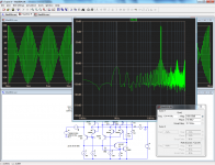
It is just an experimental OP stage, not a complete amplifier. The gain is something like -0.00001dB, the power achievable on 8 ohm with these devices is ~60W and the slew rate 14V/µsBy simple curiosity, what is the slew rate of your last schematic, and, for the reader, power and gain ?
Not the same level of the result, not the same delays before subtraction. There is a big difference in the signal to be proceeded by the input of an inverting OPA and a non inverting one. And you can measure-it if you don't ear the difference.The result of the subtraction always has to be processed by an active device.
The aura is on the differential Voltage VFB configuration, quasi monopolistic on the market ! And about merit, i had changed my mind so many times during my life...What I don't like is the craze and aura about it: I judge things on their merit, and I think in this case it is vastly overrated.
Elvee, i don't want to ague endless, as about (boring) electrolytic caps, neither to convince-you of anything. I'm old, it doesn't amuse me anymore. It is your choice to find something interesting in my comments or not. I'm just somebody different from you with long -and i believe honest- experience, both as a electronic designer and sound engineer.
On my side, i read yours with interest and have already found some very interesting things in some of your schematics and some not conventional approaches.
And about your last schematic, please, think about slew rate and the related TIM at high levels.
EOT for me.
Resistors per se do not change anything. The way signals are applied to an active device does matter.Not the same level of the result, not the same delays before subtraction. There is a big difference in the signal to be proceeded by the input of an inverting OPA and a non inverting one. And you can measure-it if you don't ear the difference.
The case of inverting vs non-inverting is well known and documented, differences are caused mainly by the absence/presence of a common-mode voltage.
Components themselves are agnostic, and in my approach, I am agnostic too.
Contrary to what many folks believe, driving a transistor from its emitter or base makes no speed difference. One could even argue based on a wave model that driving via the base is faster by a few picoseconds, but in reality it doesn't matter.
What counts is the real circuit, impedances, signals, etc, not the labels you put on a configuration or another.
VFB being mainstream and run of the mill, it has no aura, and for this reason, it is despised by some "elitists". As is global negative feedback for example.The aura is on the differential Voltage VFB configuration, quasi monopolistic on the market ! And about merit, i had changed my mind so many times during my life...
TIM is an old red herring, but an amplifier would need to be much worse than 14V/µs to show the effect. In addition, this OPS uses low grade devices and a brutal compensation scheme which could easily be upgraded, but nevertheless it is entirely fit for audio, and wouldn't be pushed to its limits even in demanding situations: the distortion at 20KHz is only marginally higher than at 1KHz (even if does not really matter), and the IMD at 20KHz is even lower, at a nice -120dBAnd about your last schematic, please, think about slew rate and the related TIM at high levels. EOT for me.
Attachments
Esperando,
I completely agree with you that CF amps sound generally considerably better than VF amps, much more involving and engaging, yet not fatiguing at all. Unfortunately I do not have one, but intend to buy it. One recent example that I heard is Cyrus Straight Line which is their only CF amp. It sounds much better than any of their VF amps.
But I am in doubt if it is gain peaking, that Mark Alexander describes as peculiarity of most CF amps in Apendix of his CF App. Note for AD, that I like?
Esperando,
I completely agree with you that CF amps sound generally considerably better than VF amps, much more involving and engaging, yet not fatiguing at all. Unfortunately I do not have one, but intend to buy it. One recent example that I heard is Cyrus Straight Line which is their only CF amp. It sounds much better than any of their VF amps.
But I am in doubt if it is gain peaking, that Mark Alexander describes as peculiarity of most CF amps in Apendix of his CF App. Note for AD, that I like?
Since model 3 which is 20 years old, Cyrus has only made CF amps so probably you were already comparing differences between CF amps and not VFB vis CFB.
...............Cyrus Straight Line which is their only CF amp................
which is correct?Since model 3 which is 20 years old, Cyrus has only made CF amps ...........
I have read Cyrus' literature and cannot recall many/some references to current feedback.
Hi, ivanlukicBut I am in doubt if it is gain peaking, that Mark Alexander describes as peculiarity of most CF amps in Apendix of his CF App. Note for AD, that I like?
Have a look to this thread: http://www.diyaudio.com/forums/solid-state/193923-simple-symetrical-amplifier-new-post.html
About Mark Alexander amp, it is a special kind of approach. He used an integrated circuit as an input device, current feedback, with some kind of error compensation: As the efficiency of the OPA decreases with frequency, the current mirror sensing its consumption increase the level, increasing bandwidth.
I had build one, at this time, and it was sounding very good, indeed. "Involving and engaging, yet not fatiguing at all" as you describe. This can apply to my actual amp, as well.
An other approach to that kind of easy and fast reproduction feeling can be a good class D, like the Hypex NC400. Andrej Lakner, the author of SSA said, comparing it with his curent-feedback baby: "...can say firmly the amps are similar in character and musical presentation in general. From there on, subtle differences are noticeable, some in a favor to NC400, some to SSA, have to be fair and honest."
You can rely on him, about "subtle": He has golden ears. And use them at each steps of his designs.
When two amps with so different approaches are "similar", we can believe on their transparency. That kind of transparency i had never heard with VFB, smooth or harsh. That kind of transparency Elvee seems to don't believe in.
Last edited:
AndrewT,
After hearing how good Cyrus Straight Line sounded I contacted Cyrus to find out if newer products are CF and they said that they are VF! I only have schematics of Cyrus 3i and it seems to be CF though producer does not explicitly mentions it.
Please note that I am not engineer, I do not have neither knowledge nor means (lab) to prove anything but my subjective preference is for CF. And that is very consistent impression from product to product, through the years.
Readers of this thread may find it helpful to know that recent Arcam A28, and probably A38, use Alexander CF circuit although this is not explicitly mentioned anywhere! The only important difference is that Arcam use bipolar Sanken Darlington output instead of Toshiba IGBT in Alexander's original circuit.
I believe that superb sound of CF is due to high gain at HF, that the sound of CF is frequency response related. But VF circuits can achieve similar results albeit only in ICs. In my opinion LM3886, although VF, sound similar to CF, because of high HF open loop gain. Since everything is packed in such small area HF losses are much lower and sound is much more similar to CF.
To Elvee Before Closing the Topic
Good question, is the CFB topology superior, and why?
It seems the thread is not moving to an answer. I don't seek an answer here as I think I know it by ears.
I mean, long time ago when people preferred BJT over MOSFET, I preferred MOSFET. Not because MOSFET sounds better than BJT, but because I can hear in MOSFET what I cannot hear in BJT. So I want a good MOSFET design that give the MOSFET sound character, plus those goodies that can be given by BJT amps.
Same with CFB amps. It is not true that CFB amp is better than VFB amps. But it seems that a CFB amp can give something that VFB amps cant. So what I want is a good CFB amp that is as good as the best VFB amp, plus its own good character.
I think theoretically Christophe's explanation did make sense, and I agree. But I don't care with theory. Just give me your best VFB amp so I can listen and see if it can give what a CFB can.
Very often, people have different opinions (and never agree with each other) simply because they have different hearing skill. Who knows this is the case here? Giving an amp example will clear the doubt.
- Status
- This old topic is closed. If you want to reopen this topic, contact a moderator using the "Report Post" button.
- Home
- Amplifiers
- Solid State
- Is the CFB topology superior, and why?