And tried to get rid of this scheme, reactive elements, as far as possible.
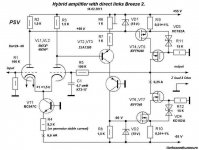
The most popular of the developments. Unlike its predecessor - this amp Breeze is easily configurable.
very nice
how about thermal stability? which transistors should be thermal coupled?
Stability is very high, due to the inclusion of a cascode output transistors! Current set almost cold transistors on which small voltage drop determined Zener diodes. These diodes regulated / restricted, and the maximum output pulse current. While gently.
One shot killed three hares - cascode switch the order of linear, broadband, far higher thermal stability than a single stage with a common source.
One shot killed three hares - cascode switch the order of linear, broadband, far higher thermal stability than a single stage with a common source.
The output stage of class "AB". Cascode switch enables this mode. Preliminary stages - Class "A"
R6 zero balance control on the amplifier output.
Sometimes it is necessary to fine-tune the balance. To do this, R3 also make the trimming.
R4 sets the quiescent current of the circuit. If the power supply stabilized, then R4 is desirable to replace the generator current.
The scheme is very simple. "The design of the day off."
6N1P hardly applicable. It has a high-voltage and low slope. Fit double triode capable of operating at low plate voltages. Best 6N23P, or its equivalent, with a different pinout 6N24P.
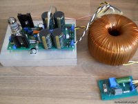
The photo Breeze-2 assembly.
http://devicemusic.ucoz.ru/_fr/0/6745242.jpg
R6 zero balance control on the amplifier output.
Sometimes it is necessary to fine-tune the balance. To do this, R3 also make the trimming.
R4 sets the quiescent current of the circuit. If the power supply stabilized, then R4 is desirable to replace the generator current.
The scheme is very simple. "The design of the day off."
6N1P hardly applicable. It has a high-voltage and low slope. Fit double triode capable of operating at low plate voltages. Best 6N23P, or its equivalent, with a different pinout 6N24P.
The photo Breeze-2 assembly.
http://devicemusic.ucoz.ru/_fr/0/6745242.jpg
Last edited:
Nice prototype...i got your point....i got 6n6p tube on hand but lowish mu of around 20....will it capable enough of driving the output at full power? how much power does it capable, if I'm not mistaken based on the rail voltage its around 100w at 8 ohms...good enough for my need..
One more thing....thermal runaway... this vertical mosfet needs thermal compensation...in this schema it doesn't have....is there no need for it?
One more thing....thermal runaway... this vertical mosfet needs thermal compensation...in this schema it doesn't have....is there no need for it?
Power will be less. But you can start with this tube.Nice prototype...i got your point....i got 6n6p tube on hand but lowish mu of around 20....will it capable enough of driving the output at full power? how much power does it capable, if I'm not mistaken based on the rail voltage its around 100w at 8 ohms...good enough for my need..
In this circuit, temperature compensation is required.One more thing....thermal runaway... this vertical mosfet needs thermal compensation...in this schema it doesn't have....is there no need for it?
Current stability is determined by the output stage transistors included common-source (the first in the course of the output stage). They drop a few volts and dissipates very little power.
Therefore the stability of the high. Plus the effect of thermal stabilization MOSFET. Plus a stabilizing effect R9R10.
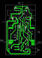
Printed circuit board is the original version.
Photos in the collection of one of the options.
Attachments
Last edited:
Thanks...as i see in your prototype...r9 and r10 needs be a TO-220 type...VT2 and Vt3 will share the same heatsink with 4 output mosfets?
Do you have the Power supply and speaker protection schematics as in the pix...in the pcb..you had already removed the PSU caps...
I can see rather that VT4,6 need small heatsinks and VT5,7 are on main heatsink...
At the general big radiator should only output transistors VT5VT6. On the radiator is the potential output. Fixing these transistors directly on the radiator. The radiator must be isolated from the housing.Thanks...as i see in your prototype...r9 and r10 needs be a TO-220 type...VT2 and Vt3 will share the same heatsink with 4 output mosfets?
The numbering of the output transistors from the top down.
A little unclear about the caps that we have in mind.Do you have the Power supply and speaker protection schematics as in the pix...in the pcb..you had already removed the PSU caps...
The maximum power of the amplifier 120 W at 8 ohms. With the supply voltage + -55 V.
Last edited:
6N23R really one of the low-voltage tubes.
At its base was made with the working tube 6N27P anode voltage from 6.3 to 30 V.
The voltage can be increased.
It will be necessary to increase the nominal R4 to 12 kohms. Current to the first stage (6.7 mA) is not changed. Still need to increase the heat transistors operating output. May need to use a cooler.
The amplifier has a soft limit of output voltage.
Therefore, it does not need power reserve.
In IRF610/9610 small current, only 3.5 A.
IRF540/9530 well suited as T4, T7. Their ultimate stress may be lower. Current shall not be less than the T5, T6. Zener voltages can be reduced by the application of low-voltage high-current transistors. Reduced to a few volts. According to the datasheet transistors.
IRF540/9530 well suited as T4, T7. Their ultimate stress may be lower. Current shall not be less than the T5, T6. Zener voltages can be reduced by the application of low-voltage high-current transistors. Reduced to a few volts. According to the datasheet transistors.
Zener diodes VD1 and VD2 15V extra protection gates.
These small capacity. On the operation of the circuit in normal mode is not affected.
Did not expect such an interest in the scheme. )))
The last option users make integrator. Excluded from the scheme С1. Post # 545:
http://devicemusic.ucoz.ru/forum/5-61-37
These small capacity. On the operation of the circuit in normal mode is not affected.
Did not expect such an interest in the scheme. )))
The last option users make integrator. Excluded from the scheme С1. Post # 545:
http://devicemusic.ucoz.ru/forum/5-61-37
Last edited:
Hi, Pawel!
First selected tubes. To do this on the board or on the layout is going to the first cascade. The difference current shoulders should be small. Desirably less than 10%. Control is maintained by the voltage at R2, R3. And the cathode voltage. Sometimes you need to do trimming R3. Then replace it with a fixed resistor.
Usually from 8-10 new tubes 6N23P or 6N24P two form a good pair.
Then going full scheme. Resistor R6 shoulders balanced current output. R4 determines the quiescent current scheme.
So briefly.
P.S. This current amplifier. Output current proportional to the input voltage.
Last edited:
- Status
- This old topic is closed. If you want to reopen this topic, contact a moderator using the "Report Post" button.
- Home
- Amplifiers
- Solid State
- Hybrid amplifier with direct links Breeze 2.