Sounds like you got away with that one. If an output transistor had blown it wouldn't work and there would be obvious signs of distress.
(I've deleted your post in the pictures thread as you have started ths one.)
You asked how to post pictures ?
Too add a photo,
First click "go advanced" in the box below the "quick reply" message box. Doesn't matter if you decide half way through a message to do that, it carries it foward.
Then click "Manage attachements"
Click browse in the first box at the top and find your picture. Repeat for any more pictures.
Click upload... a message appears "uploading"
When complete, scroll down to the bottom of page and click "close this window"
The pictures should now be attached and when you post will appear. I don't think they show in message preview... they never used to anyway.
Make sure your pics aren't too big, a couple of 100k is plenty, and many object when they are massive and it alters the margins
It tells you in the attachments window what max sizes are allowed.
Without a manual you don't know what the recommended bias is. So first thing is to mark the position of the pots so you can put them back where they are.
The DC offset pots will usually be around the input circuitry side of the amp. Adjust for 0.00 DC volts across the speaker terminals.
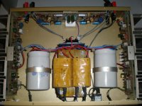
Bias is usually checked by measuring the voltage across some low value resistor and calculating the current. Maybe those four wirewond resistors I can see. There would be one in each output transistor "emitter" connection. I would guess they are around 0.1 to 0.22 ohms in value.
There are various ways of determining the correct bias but we would need to see the circuit for that. If in doubt aim low and make sure it doesn't drift upward. The value could be as low as 20ma or so.
A bulb tester in series with the mains might be an idea until you identify all the pots. Also have no speakers connected for these adjustments.
The DC offset pots will usually be around the input circuitry side of the amp. Adjust for 0.00 DC volts across the speaker terminals.
Bias is usually checked by measuring the voltage across some low value resistor and calculating the current. Maybe those four wirewond resistors I can see. There would be one in each output transistor "emitter" connection. I would guess they are around 0.1 to 0.22 ohms in value.
There are various ways of determining the correct bias but we would need to see the circuit for that. If in doubt aim low and make sure it doesn't drift upward. The value could be as low as 20ma or so.
A bulb tester in series with the mains might be an idea until you identify all the pots. Also have no speakers connected for these adjustments.
Hey Mooly , Thanks for your help!
The four wire wounds ? Is that those wight resisters about 3/4'' long? So those pots on the output board are not for bias? Ok the pots on the input board is should be set a 0v . Put my tester leads +to+ and -to - on the speaker post ? Amp on or off? Also can you explain in more detail? Im really trying to do this myself , being we have no techs here where I live , it sucks ! Iv bin into gear my hole life but really have never learned any of the this . I was worried when I bout this , do to age ! The guy said it was fully checked and serviced .
Well anyway do you think that stunt on did would have anything to do with getting the bias off?
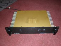
Without a circuit diagram we are guessing as to the exact function of all the pots. Without having the unit in front of me its impossible to make out. Those on the rear panel ?? might be to set a stabilised voltage (a voltage regulator).
What you can do is measure the DC voltage across the speaker terminals with the amp on. It should be under 50mv. Lets confirm what the offset voltages are first.
Also with the amp on measure and record the voltage across each of those four white wirewound resistors (the big white ones ). The channel that runs hottest will have the largest voltage. The voltage across each pair of resistors in each channel should be equal. The voltage will be small, probably in the millivolt region assuming these resistors are what I believe they are. Be very careful not to short anthing making the measurements. The pots (what look like pots anyway in the pic) on the two side panels are probably bias but don't alter anything yet.
What you can do is measure the DC voltage across the speaker terminals with the amp on. It should be under 50mv. Lets confirm what the offset voltages are first.
Also with the amp on measure and record the voltage across each of those four white wirewound resistors (the big white ones
). The channel that runs hottest will have the largest voltage. The voltage across each pair of resistors in each channel should be equal. The voltage will be small, probably in the millivolt region assuming these resistors are what I believe they are. Be very careful not to short anthing making the measurements. The pots (what look like pots anyway in the pic) on the two side panels are probably bias but don't alter anything yet.Without a circuit diagram we are guessing as to the exact function of all the pots. Without having the unit in front of me its impossible to make out. Those on the rear panel ?? might be to set a stabilised voltage (a voltage regulator).
What you can do is measure the DC voltage across the speaker terminals with the amp on. It should be under 50mv. Lets confirm what the offset voltages are first.
Also with the amp on measure and record the voltage across each of those four white wirewound resistors (the big white ones
Attachments

Ok I checked the dc offset from the rear pots and the cold side 18 and there warm side was 3 so adjusted them both for around 15mv. Now the bias is done on those transistors , but what should i set my meeter at and How show I put my leads . Thanks for your help, i went to my local tech today and he said he could not help! Mooly if we can talk over the phone that would be great ?? This is my email for my number. If so ! hemihead05@yahoo.com
Without a circuit diagram we are guessing as to the exact function of all the pots. Without having the unit in front of me its impossible to make out. Those on the rear panel ?? might be to set a stabilised voltage (a voltage regulator).
What you can do is measure the DC voltage across the speaker terminals with the amp on. It should be under 50mv. Lets confirm what the offset voltages are first.
Also with the amp on measure and record the voltage across each of those four white wirewound resistors (the big white ones
Hi,
You'll be fine doing as outlined here, and putting it all on the forum helps others
OK, so I'm a little confused as to what you have actually measured and adjusted.
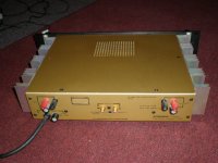
1. The DC offset is measured on the speaker terminals on the back of the amp (you mention the "DC offset from rear pots" ?). So you put the meter on DC volts and connect the red meter lead to the red speaker terminal and the black meter lead to the black speaker terminal for one channel. The voltage you measure is called the DC offset and should be as low to zero as possible. Anything less than 50 millivolts is good.
2. Next you connect the meter leads ACROSS any of those four resistors. Those horizontal ones at the front of the amp seem the easiest to get to. The DC voltage you measure here can be converted to a bias current (by using ohms law). Repeat the measurement for the same resistor on the other channel. It doesn't matter which way round the meter leads are for this.
Also what is the value of these resistors ? What are the markings ? Measuring the value may not be accurate if you are not used to measuring really low value resistors in circuit as the meter lead resistance can be nearly as much as the resistor itself. So what are the markings
You'll be fine doing as outlined here, and putting it all on the forum helps others
OK, so I'm a little confused as to what you have actually measured and adjusted.
1. The DC offset is measured on the speaker terminals on the back of the amp (you mention the "DC offset from rear pots" ?). So you put the meter on DC volts and connect the red meter lead to the red speaker terminal and the black meter lead to the black speaker terminal for one channel. The voltage you measure is called the DC offset and should be as low to zero as possible. Anything less than 50 millivolts is good.
2. Next you connect the meter leads ACROSS any of those four resistors. Those horizontal ones at the front of the amp seem the easiest to get to. The DC voltage you measure here can be converted to a bias current (by using ohms law). Repeat the measurement for the same resistor on the other channel. It doesn't matter which way round the meter leads are for this.
Also what is the value of these resistors ? What are the markings ? Measuring the value may not be accurate if you are not used to measuring really low value resistors in circuit as the meter lead resistance can be nearly as much as the resistor itself. So what are the markings
Hi,
You'll be fine doing as outlined here, and putting it all on the forum helps others
OK, so I'm a little confused as to what you have actually measured and adjusted.
1. The DC offset is measured on the speaker terminals on the back of the amp (you mention the "DC offset from rear pots" ?). So you put the meter on DC volts and connect the red meter lead to the red speaker terminal and the black meter lead to the black speaker terminal for one channel. The voltage you measure is called the DC offset and should be as low to zero as possible. Anything less than 50 millivolts is good.
2. Next you connect the meter leads ACROSS any of those four resistors. Those horizontal ones at the front of the amp seem the easiest to get to. The DC voltage you measure here can be converted to a bias current (by using ohms law). Repeat the measurement for the same resistor on the other channel. It doesn't matter which way round the meter leads are for this.
Also what is the value of these resistors ? What are the markings ? Measuring the value may not be accurate if you are not used to measuring really low value resistors in circuit as the meter lead resistance can be nearly as much as the resistor itself. So what are the markings
The resisters say 22 ohms 10% all 4 08 8 ! I did check a couple , and one I can not get to! My put tester on 200mv that's the lowest it will go, and I get different readings for and then when I go back there different again. # 1 spikes to 10.5 then 6.5. then back and forth . The others also go up to 8 ish or so . and 6.6.. How do I even know what side needs the work ,the warm side or cold side ? The warm side had the low dc os and cooler side had the os at 18.? When I checked for dc os I had my meeter on 200m is that rt? also what would cause it drift anyway?
Mike
Last edited:
For Dc off set what should I set my VM at ? 200mv 20mv or 2000mv ? Also if drift up and down what do i do? If I set to 2000mv it show like 1,2,3 and so on,when I set if for 200mv it shows 1.1, and its very touchy ! I hear that the amp should run worm ,for this one anyway. The side that is cool , do you think the bias needs to be raised ? How do I know what chan is correct ? The cool side did have work done to it 6 months ago.Maybe the guy did not set rt cause the dc offset was 18. and the warm side 3 witch be good!Hi,
You'll be fine doing as outlined here, and putting it all on the forum helps others
OK, so I'm a little confused as to what you have actually measured and adjusted.
1. The DC offset is measured on the speaker terminals on the back of the amp (you mention the "DC offset from rear pots" ?). So you put the meter on DC volts and connect the red meter lead to the red speaker terminal and the black meter lead to the black speaker terminal for one channel. The voltage you measure is called the DC offset and should be as low to zero as possible. Anything less than 50 millivolts is good.
2. Next you connect the meter leads ACROSS any of those four resistors. Those horizontal ones at the front of the amp seem the easiest to get to. The DC voltage you measure here can be converted to a bias current (by using ohms law). Repeat the measurement for the same resistor on the other channel. It doesn't matter which way round the meter leads are for this.
Also what is the value of these resistors ? What are the markings ? Measuring the value may not be accurate if you are not used to measuring really low value resistors in circuit as the meter lead resistance can be nearly as much as the resistor itself. So what are the markings
Thanks Mooly
I think those resistors are going to be 0.22 ohms (which would be a typical value).
First point.
It's normal to see different DC offset values between the channels and the absolute value has no bearing on how hot that channels runs. All we need to be sure of is that the offset is acceptably low (less than 50millivolts DC). It's also normal for the value to drift as the amp stabilises and warms. So if the value (for example) starts at +40mv and falls and passes through zero and settles at say -28mv then that's fine.
The bias is the small current that always flows in the output transistors. This value also drifts as the amp warms up and most procedures will say to set it and then recheck after say 30 minutes etc. Without the service manual we can only follow normal good practice and set it for a "typical" value. If we say 20millamps then that means setting the bais to give around 4.5 millivolts across the 0.22 ohm resistors.
Without knowing more about the amp and the circuitry we can't say more than that. A lot depends on the output stage topology and the devices fitted (whether transistor or FET's)
For Dc off set what should I set my VM at ? 200mv 20mv or 2000mv ? Also if drift up and down what do i do? If I set to 2000mv it show like 1,2,3 and so on,when I set if for 200mv it shows 1.1, and its very touchy ! I hear that the amp should run worm ,for this one anyway. The side that is cool , do you think the bias needs to be raised ? How do I know what chan is correct ? The cool side did have work done to it 6 months ago.Maybe the guy did not set rt cause the dc offset was 18. and the warm side 3 witch be good!
Thanks Mooly
Your meter has to be on whatever range gives the best resolution for the task at hand. If the amp has a reputation to run hot then the bias is probably more correct in the hot channel and you could alter the cool to match by setting the voltages across the 0.22 ohms to equal that channel.
And remember the DC offset doesn't affect this setting or how hot the amp runs.
What would i set my volt meeter at do this 200mv,20,or 2000? also yes they are 22ohms ! How do i use the pot if i ck each resister ? What would i set that at?I think those resistors are going to be 0.22 ohms (which would be a typical value).
First point.
It's normal to see different DC offset values between the channels and the absolute value has no bearing on how hot that channels runs. All we need to be sure of is that the offset is acceptably low (less than 50millivolts DC). It's also normal for the value to drift as the amp stabilises and warms. So if the value (for example) starts at +40mv and falls and passes through zero and settles at say -28mv then that's fine.
The bias is the small current that always flows in the output transistors. This value also drifts as the amp warms up and most procedures will say to set it and then recheck after say 30 minutes etc. Without the service manual we can only follow normal good practice and set it for a "typical" value. If we say 20millamps then that means setting the bais to give around 4.5 millivolts across the 0.22 ohm resistors.
Without knowing more about the amp and the circuitry we can't say more than that. A lot depends on the output stage topology and the devices fitted (whether transistor or FET's)
Thank man!
huge help!
Normally we use the range that gives best resolution. For example to read 12.3 millivolts and using a 200mv rangle on a simple DVM we should read say 12.3mv. On a 2 volt range it would be showing only 0.01 which isn't accurate in resolution. 8 mv or 15 mv might still only show as 0.01
Do you see ? And 20mv or 25 mv would only register 0.02 and so on. There's no resolution. So we keep turning the range down until we make most use of the available digits and resolution.
Do you see ?
And 20mv or 25 mv would only register 0.02 and so on. There's no resolution. So we keep turning the range down until we make most use of the available digits and resolution.Hmmm, lol ,ok my meeter says 200m,2000m,20,200,1000, I have bin putting on 200m and trying to get as close to 0 as possible , Like high 1.0 and low -0.08 ?
Yes it is very sensitive, tough ! If I move it 2000, it seems like Im turning much more .
So im thinking since mv is very tine ,I would use 200m is the lowest setting I have ?
Yes it is very sensitive, tough ! If I move it 2000, it seems like Im turning much more .
So im thinking since mv is very tine ,I would use 200m is the lowest setting I have ?
Last edited:
The amp is a Audionics cc3 power amp , How would I get the bias set for each resister with one pot and how many dcv do u think they should be set at?Hmmm, lol ,ok my meeter says 200m,2000m,20,200,1000, I have bin putting on 200m and trying to get as close to 0 as possible , Like high 1.0 and low -0.08 ?
Yes it is very sensitive, tough ! If I move it 2000, it seems like Im turning much more .
So im thinking since mv is very tine ,I would use 200m is the lowest setting I have ?
Hmmm
Maybe doing some reading on power amplifier design would help you understand all this.
There will be one pair of resistors per pair of output transistors, and the voltage across each should be approximately the same. The one bias pot alters the conduction point of the output transistors and they all pass the same current hence the voltage across each resistor is the same too.
Doug Selfs book on power amplifier design would be a great help to you in understanding all this.
- Status
- This old topic is closed. If you want to reopen this topic, contact a moderator using the "Report Post" button.
- Home
- Amplifiers
- Solid State
- Audionics from Oregon CC3 power amp