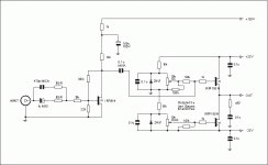
The 4,7V zeners have approximately the same Tc as the Vgs of the IRF150's. So once DC adjusted it will keep fairly DC stable.
It's easy and cheap to build, fun to play with, and sounds great, with all the good properties of a single end amp. (everything sounds pleasant, and recording flaws are left out of focus).
I hope somebody out there will find it interesting, and i'd love to hear your comments!
All the best.......
Lars Clausen
Attachments
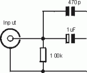
btw. You should connect this 100k resistor across the input RCA, it will prevent the amp from popping if you should start it up with no input connected, and then connect a signal source while the power is still on.
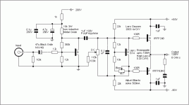
The trick that makes this amp so special is that the first stage (much resembling a Zen stage) has vast amounts of second order distorsion. The second stage (the output stage) also has vast amounts of second order distorsion, but in a reversed phase, so the two distorsions tend to null each other out. A distorsion reducing topology without the harmful global feedback loop ...
Try it, it really works!
It would also be simple to build this amp as a 100W Class A/B with a different output stage, i will post on this thread later.
Attachments
So here it is, a 138W in 8 Ohms A/B amp.
How do we keep the second order distortion down? Well only by using a small portion of the input stages rail to rail amplitude, simply by increasing the voltage supply to that stage radically.
To avoid the MOSFET's low ID distortions, you should adjust the bias to a relatively high level, of 500 mA. Mount the BIAS MOSFET IRFI614 on the heatsink, in close proximity to one of the power FET's, then it should be 100% thermally stable. Use a big heatsink, as you will have to dissappate up to 100W of heat from the power MOSFET's. 0.33 C/W should be adequate.
Some would use a feedback loop to get rid of cross over distortion, but in my view loops only remove measurement distortion, and still causes the sound to get blurred and fuzzy. Unless you have a very low time delay in your feedback loop of course, say less than 0.5 uS. Nearly impossible in an analog design.... Another thing about feedback loops is that they are a constant source of load dependant instability, that's why you always see loads of small capacitors in the amplifier circuit, and an air coil in the output stage. In this non-feedback design .. it's just not nessescary, as it has no feedback loops to make it unstable.
Have fun with this one .. ;-)
Attachments
About high frequency rolloff
Hi. I want to build a similar amp, with diff amp on input, and second stage power follower ( single ended ). My question: did you measure a frequency range, especially on the top. IRFP150 have a quite high input capacitnce, and output impedance of yours voltage stage is about 10k Ohm, WHAT ABOUT HIGH FREQENCIES ? In my amp I want to use a 3,3k Ohm resistors as a drain load of diff amp, and irf520 as follower transistor ( input capacitance about 3 times lower, but transconductance lower too..).
There is a posibility to place a negative feedback in my amp, and will do it. Open loop gain about 30 V/V ( Rd = 3,3K, Rs = 47R ) and close loop about 12V/V.
If you could write something about measurments, i would be greatful.
I built it some months ago, and it measured from 5 - 34.000 Hz within 3 dB. Not exactly infinite bandwidth, but enough to facilitate most uses. You can speed it up, but you could be digging out some degrading new sound properties, when using this type of circuit. I like the simplest possible solution, which is possible just when you are building a small amplifier with only the most nessescary functions.
It is not a technical data giant, but it is simple to build, and plays with a nice relaxed sound.
I have built audio amplifiers in the past with 3 dB linearity from DC to well over 2 MHz, however you would have to use other types of parts, and circuits, and you will end up with an amplifier focusing on micro details, and very revealing to amy flaws in the source signals. This amp though is more relaxed and forgiving towards the source material.
IRFI614, you can find the datasheet at
http://www.irf.com/product-info/datasheets/data/irfi614g.pdf
i did not try to replace it with other types, but i guess anything with a low Cdg (reverse transfer capacitance), and 250 V breakdown voltage might be usable.
All the best from Denmark....
- Status
- This old topic is closed. If you want to reopen this topic, contact a moderator using the "Report Post" button.
- Home
- Amplifiers
- Solid State
- 17 W Single Ended Solid State Power


