I hope this post is in the right place? I couldn't find anywhere else to put it! I'm trying to repair this receiver for a friend,it came to me with a burnt out power supply that was caused I suspect from the conductive brown glue they used in those days,I have cleaned up the glue and recapped the amplifier and tuner completely.This model is from late 70s / early 80s and has an MSU digital controller for functions FM, AM, AUX, PHONO (not working) I suspect that the MSU (MN1455LF) has failed! What I need to know is can I replace the MSU without having to program it? I'm hoping that I can solder in a socket and just plug another MSU in! I have only ever repaired analog amps before,I would appreciate any suggestions, advice, ideas ect...
Normally the microprocessors are the last to suspect.
My tactics for dealing with anything like that is to have the service manual in front of me and then go along every pin with a scope and DVM and make sure that what you see and read is what would be expected.
As jaycee says, the IC has to be correct type and it's the numbers after the main device number that matter as these are the unique program burnt into the ROM of the chip.
Ive changed all dodgy components transistors,diodes ect..checked and rechecked voltages everything adnauseum,so that all voltages where correct, I turned it on and it still didn't work,after I had calmed down a bit I turned it back on and Begorrah! It was working! I left it on for about 4 hrs FM & AM worked in fact it sounded excellent.After turning it on & off a few times with it still working I noticed it was intermittently cutting out for a fraction of a second I had a look and found a connector ribbon had a broken wire and was just resting there,it is the 5v power for the MCU I fixed that and f#@%$# me dead I was back to where I started except when I plug it in now the relay hums and chatters so I give the speaker relays a rap with my knuckles and the amp comes on but not the radio or function side of things. Any ideas I could try next fellas?
It all sounds as though there is something physically intermitent. So after fixing this broken ribbon it now doesn't work ?
If a relay hums its usually because of a problem with the drive to it so check the supplies feeding it. Maybe there is a problem/dry etc with a smoothing cap on a rail. The relay coil won't hum with pure DC.
If a relay hums its usually because of a problem with the drive to it so check the supplies feeding it. Maybe there is a problem/dry etc with a smoothing cap on a rail. The relay coil won't hum with pure DC.
It all sounds as though there is something physically intermitent. So after fixing this broken ribbon it now doesn't work ?
If a relay hums its usually because of a problem with the drive to it so check the supplies feeding it. Maybe there is a problem/dry etc with a smoothing cap on a rail. The relay coil won't hum with pure DC.
Thanks mate! Your advice did the trick,I followed the circuit and found a shorted diode in the power supply that I had replaced before thinking it was blown originally when I got the receiver ,so I looked a bit further and found that when I recapped it I have used a 470uf cap instead of a 330uf cap.Duh! I have ordered the cap and should get it in a week or two,I live in regional Western Australia and it comes from Eastern Australia.I would say that this would be the problem ay?
The shorted diode will be the problem.
The difference between 330 and 470uf won't make any difference tbh. The tolerance on electros used to be +100 and - 50%")
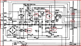
Well here I am again, all confused.I went thru all the old caps so I could try the 330uf cap back in it but there wasn't one there? I had recapped cap for cap and it looks like the service manual has got it wrong again! What I have now is 12voltsDC on transistor Q820 its collector its supposed to be 0.38? I'm reading about 9vAC on that collector as well (R915 2W) is actually a wire link, It goes to the power and speaker relays thru j823 and returns thru j829 at approx 20volts.Transistor Q820 is a new one as is Q812.What do you think?
Attachments
Firstly, all the transistor voltages are measured using DC volts ranges. (Many meters show a (meaningless) voltage reading when on AC volts ranges and they are connected to a pure DC source... its a quirk of the way many meters work... try it measuring a 9 volt battery and see)
The readings on Q820 indicate it is turned off. If so the B-E voltage will be below 0.6 volts. So check that and also see what the DC voltage is on the right hand end of the 10k resistor (R818)
Service can be wrong or sometimes you can be looking at a "regional variation" difference and the manual applies to a different variant.
Firstly, all the transistor voltages are measured using DC volts ranges. (Many meters show a (meaningless) voltage reading when on AC volts ranges and they are connected to a pure DC source... its a quirk of the way many meters work... try it measuring a 9 volt battery and see)
The readings on Q820 indicate it is turned off. If so the B-E voltage will be below 0.6 volts. So check that and also see what the DC voltage is on the right hand end of the 10k resistor (R818)
Service can be wrong or sometimes you can be looking at a "regional variation" difference and the manual applies to a different variant.
The right hand side of R818 measures 0.6v,that's when I plug the cord in and the transformer starts to hum,so I set the DMM to diode setting and touch the left hand side of R818 with the probe to turn it on.It turns on the amplifier but not the functions? Q820=B,0.06v,C,12.0v E,000v, when turned on.
The right hand side of R818 measures 0.6v,that's when I plug the cord in and the transformer starts to hum,so I set the DMM to diode setting and touch the left hand side of R818 with the probe to turn it on.It turns on the amplifier but not the functions? Q820=B,0.06v,C,12.0v E,000v, when turned on.
OK, so you are using the diode check voltage and current to turn on Q818 and in doing that it operates the relay correctly.
So from what you say it is sounding like there is a problem with/or/something stopping the correct voltages to "unmute" and to enable all the functions.
Without a full circuit its impossible to say what is going on tbh. The thing to do is concentrate on one problem.
No base drive to Q820. So you need to see what drives resistor R818 and what conditions are required for that drive. For example is it fed direct of the u-processor or off more discrete circuitry ?
The base is driven from the MSU to the left side of R818, it measures 1.7v and 0.06v on the right side! Is there any way I can send you the SM and /or schematics.If not I have uploaded them to AKs digital docs. I'm OK with analog stuff but this digital throws me when it comes to troubleshoot it.I appreciate your patience and any help you can give me.
OK... this is a complex circuit but we have to start somewhere
Remember there are no guarantees and you have the advantage of the unit in front of you
Now you say in post #6 that it did actually work allbeit briefly. So I'm assuming its still as it was back then physically.
Before doing anything remove all power and remove the backup batteries. Confirm the voltage across C823 (Q818 Emitter) is zero. If not apply a temporary short to discharge it. Remove short.
With it powered up.
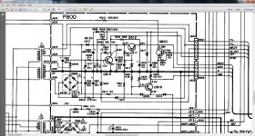
1. We need to confirm the 5.6 volt rail by measuring the voltage at Q812 emitter.
2. What is the voltage at Q818 collector. This should be at 5 volts whether plugged in or not if the backup batteries are fitted.
3. What is the voltage on pin 19 of Q501 (The micro) This pin powers two (or three if they are all physically separate) relays that provide AC power to the main transformer and the switched AC outlet on the back.
4. Q814 appears to be used to detect AC power. What is the collector voltage when plugged in.
5. Is the display lit ? Are the +28 and -28 volt rails correct. All these voltage are on the connectors W501 and W502.
The - and + 28 volts are the voltages across those two zeners.
Remember there are no guarantees and you have the advantage of the unit in front of you
Now you say in post #6 that it did actually work allbeit briefly. So I'm assuming its still as it was back then physically.
Before doing anything remove all power and remove the backup batteries. Confirm the voltage across C823 (Q818 Emitter) is zero. If not apply a temporary short to discharge it. Remove short.
With it powered up.
1. We need to confirm the 5.6 volt rail by measuring the voltage at Q812 emitter.
2. What is the voltage at Q818 collector. This should be at 5 volts whether plugged in or not if the backup batteries are fitted.
3. What is the voltage on pin 19 of Q501 (The micro) This pin powers two (or three if they are all physically separate) relays that provide AC power to the main transformer and the switched AC outlet on the back.
4. Q814 appears to be used to detect AC power. What is the collector voltage when plugged in.
5. Is the display lit ? Are the +28 and -28 volt rails correct. All these voltage are on the connectors W501 and W502.
The - and + 28 volts are the voltages across those two zeners.
Attachments
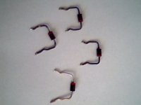
I shorted C823, then measured Q818, it reads zero on its emitter with all power off including batteries. When powered up, it measures (Q812, E,-5.6v.) (Q818, C, 5v.) (Q814, C, 4.8v.) Pin19 is 4.8v. 28v rails measured across the zeners are +30.1v and -28.7v. The display is lit up but not working. I just cleaned up the blackleg oxide on the rectifier diodes (it cant be a good thing) I cleaned one up in the picture to show you how bad they were. After doing that I turned it on to see if there was any difference? About a minute later I heard two electrical arc type high current cracks in quick succession! After my nervous system had got itself together again LOL I tried turning it on with a bulb in series,to my surprise nothing seems to be damaged,it is still exactly the same.I think the sound may have come from the power relays? The power relays are all separate (3).OK... this is a complex circuit but we have to start somewhere
Remember there are no guarantees and you have the advantage of the unit in front of you
Now you say in post #6 that it did actually work allbeit briefly. So I'm assuming its still as it was back then physically.
Before doing anything remove all power and remove the backup batteries. Confirm the voltage across C823 (Q818 Emitter) is zero. If not apply a temporary short to discharge it. Remove short.
With it powered up.
1. We need to confirm the 5.6 volt rail by measuring the voltage at Q812 emitter.
2. What is the voltage at Q818 collector. This should be at 5 volts whether plugged in or not if the backup batteries are fitted.
3. What is the voltage on pin 19 of Q501 (The micro) This pin powers two (or three if they are all physically separate) relays that provide AC power to the main transformer and the switched AC outlet on the back.
4. Q814 appears to be used to detect AC power. What is the collector voltage when plugged in.
5. Is the display lit ? Are the +28 and -28 volt rails correct. All these voltage are on the connectors W501 and W502.
The - and + 28 volts are the voltages across those two zeners.
Attachments
Last edited:
Just strapped for time at the moment...
Q812 E. Plus 5.6volts yes
Other voltages seem reasonable apart from Q814. We'll come back to that.
Obvious voltage that stands out is pin 19 at 4.8 volts. That sounds right. That voltage goes directly to Q820 via R818. So the collector of Q820 should be near zero (Check it !)and the relays turned on and yet they are not. Carefull measurements are everything. The base-emitter volt drop of Q820 must be around 0.7 volts. Check by measuring across the pins of the transistor.
The main relays can be forced on by applying a direct short across Q820 E and C to turn the relays on permanently. I would advise the bulb tester be used. Might be worth tryin if you find nothing amiss.
I'll take a closer look later...
oh and the diodes... that's normal on many old parts. I've seen it many times.
- Status
- This old topic is closed. If you want to reopen this topic, contact a moderator using the "Report Post" button.
- Home
- Amplifiers
- Solid State
- Marantz SR8100dc, advice needed.