The collector of Q820 measures 9-12v.its base to emitter measurement is .673v. I should mention the power relays will click in sometimes after about 30 seconds?
The B-E volts suggests Q820 should be fully on.
If Q820 collector is reading anything other than near to zero volts when pin 19 of the uP is at 19 volts then there is a problem.
I suspect there are going to be other issues too but this is one definite problem. Providing there is nothing physically wrong with the PCB and connectivity then Q820 appears faulty. It has to turn on fully given 19 volts on pin 19.
(And just trying to cover all bases on this... without a scope check on pin 19 we are assuming it is DC (it should be) but what if it is not ? That could cause a DVM to give a misleading reading. So another check could be to connect a 10K resistor from the base of Q820 to the 5.6 volt rail to force Q820 into conduction. That should fire the relays instantly.
I would normally use a scope for all the DC measurements on a fault like this as it lets you see other problems such as noise on the rails)
Hi Karl,The Q820 measurement B-E was done with a DMM when the unit was off unplugged with no battery's installed and the collector of Q820 measures 8v-12v the voltage keeps changing on it?. Pin 19 on the MCU is actually 4.6v-4.8v.Not 19 volts. Ive been trying to work this amp out for about two months now and I got a bit flustered & frustrated the other day but I'm OK now.
Thats my mistake typing 19 volts.
All the above still applies though. With the unit on and pin 19 at 4.8v ish") then Q820 must be fully on and its collector should be at near zero volts. In turn that should pull the relays in. If the collector is not at zero and the relays are not pulled in then this becomes a way into the fault/s as its a part of the circuit that should operate in isolation. So we need to confirm this first.
then Q820 must be fully on and its collector should be at near zero volts. In turn that should pull the relays in. If the collector is not at zero and the relays are not pulled in then this becomes a way into the fault/s as its a part of the circuit that should operate in isolation. So we need to confirm this first.
As mentioned, I suspect there will be other issues but this is a way into a definite problem.
All the above still applies though. With the unit on and pin 19 at 4.8v ish
then Q820 must be fully on and its collector should be at near zero volts. In turn that should pull the relays in. If the collector is not at zero and the relays are not pulled in then this becomes a way into the fault/s as its a part of the circuit that should operate in isolation. So we need to confirm this first.As mentioned, I suspect there will be other issues but this is a way into a definite problem.
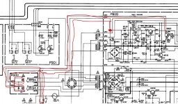
What I cant work out is where that voltage on Q820 collector is coming from? I replaced Q820 with a new one and it measures OK in and out of circuit.Another thing is, on board P500 diode Q536 someone had added a wire link from the pointy end of the diode ha! I cant remember if its the anode or cathode.To pin5 on Q501 MCU which is the high level AC outlet pin.I measured pin19 with a scope and its OK pure DC.
Q820 connects via the relay coils to the main auxilliary PSU. Thats to C821. Check the voltage there is correct. Its shown as 33 volts in the manual.
(So with Q820 OFF you should read that same voltage on the collector... yet you mention 8 to 12 volts. Something not right around there so have a measure)
(So with Q820 OFF you should read that same voltage on the collector... yet you mention 8 to 12 volts. Something not right around there so have a measure
)Attachments
Last edited:
C821 measures 24.1v on the + side. C821 is 100uf,on the schematic but is 1uf, on the parts list,I have 1uf installed currently,should I change it over to the 100uf? P.S. Diode Q815 measures 34v on its (cathode,pointy bit end) and 10.2v on Q820 collector.Q820 connects via the relay coils to the main auxilliary PSU. Thats to C821. Check the voltage there is correct. Its shown as 33 volts in the manual.
(So with Q820 OFF you should read that same voltage on the collector... yet you mention 8 to 12 volts. Something not right around there so have a measure
Last edited:
1uF sounds really low. Its function is a reservoir capacitor and at 1uf I can't see it doing anything.
It is a strange circuit. The diode Q815 and C822 (the 330uf) is the main reservoir cap for that rail and auxilliaries with the diode isolating the relay drive voltage.
What it means is that the time constant for the relay supply can be made low (so the relays drop out instantly on power disconnection, while the 330uf keeps the other rail alive a fraction longer.
1uF sounds way to low and would explain the relays humming (think you mentioned that a while back) due to the excess ripple voltage.
Try a 100uf and see what the effect of that is.
1uF sounds really low. Its function is a reservoir capacitor and at 1uf I can't see it doing anything.
It is a strange circuit. The diode Q815 and C822 (the 330uf) is the main reservoir cap for that rail and auxilliaries with the diode isolating the relay drive voltage.
What it means is that the time constant for the relay supply can be made low (so the relays drop out instantly on power disconnection, while the 330uf keeps the other rail alive a fraction longer.
1uF sounds way to low and would explain the relays humming (think you mentioned that a while back) due to the excess ripple voltage.
Try a 100uf and see what the effect of that is.
Yes that makes sense,I cant find any 100uf caps with the right voltage,only 80v,100v,160v,the 80v elna wont fit physically anyway and the 100v is getting a bit too high I think so Ill wait until the shops open in the morning & get one. Its 2.40am here,so I'm off to bed and will let you know how it went Karl.
OK that did the trick! now there's no hum at all and when I plug it in to the mains it smoothly turns on the relays and the green light is on it just takes a bit longer to turn on sometimes. J823 is measuring 12v,J829 is 32.5v? I was hoping against hope that the functions would work as well when I turned it on LOL. Oh no! I just noticed that I'm getting +52v & -53v respectively thru the top of the metal aluminum case on my main filter caps! that cant be good can it?
So that seems like one problem fixed. Those voltages sound correct now with the relay running at approx the correct coil voltage (24 volt relay... 32.5-12).
Its normal to sometimes measure voltage on the outer can of a cap... it all depends on the internal construction.
The other issues could be more difficult to find. If a lot of different functions aren't working then it's usually best to concentrate on just one and try and fault find that. Anything around the uP requires the checking of all the input and output ports as mentioned before.
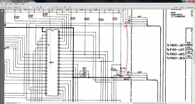
I used a digital probe on The uP Q501,it indicated an error on out going pins 8,9,10,11,12,13.This is caused I presume by errors on incoming pins from Q571 30 & 40,ref clocks.yet they measure up OK, I think? pin 30 reads,2.29v at 250 hz. pin 40 reads 2.39v at 562.5 khz.The Service Manual is all over the place & its got me confused again Ha! The reference frequency's come from Q571, MN6147,pin 5= 562.5khz, pin 6= 250hz? Do you think their voltages could be too high too low? Do you want me to post all the high & low voltages on uP?
I'll try and have a closer look tomorrow but I suspect this isn't going to be easy.
Without seeing first hand how it all behaves then its easy to go up the wrong path. When dealing with clock signals its the overall amplitude that matters. Usually it has to be within a 200mv (logic low) to 4.5 volt (logic high) volt swing. If they were only say 1 volt peak to peak in amplitude then that could indicate a problem etc. They have to be checked on scope really.
Without seeing first hand how it all behaves then its easy to go up the wrong path. When dealing with clock signals its the overall amplitude that matters. Usually it has to be within a 200mv (logic low) to 4.5 volt (logic high) volt swing. If they were only say 1 volt peak to peak in amplitude then that could indicate a problem etc. They have to be checked on scope really.
Just from having a quick look, and I know its not much to go on.
Pin 1. True ground 0.00 volts. Always confirm it is... never assume anything when faultfinding. And wherever possible use a scope for all the measurements, even for things like 5 volt rails and ground connections.
Pin 5. Seems to go back to Q814 ? in the PSU. 3.8 volts shown. Seem to remember saying we would look again at this one some time back. This could be used as an AC detect (mains present) input to the uP and so should be correct ! It can't ( or shouldn't) be an AC or pulse waveform because of the 22uf cap on Q814 collector. I would have thought nearer 5 volts than 3.8 but the readings in the manual could be quoted with the "old" standard of using a 20kohm/volt meter rather than a DVM.
Pin 39. "All time" 5 volts. Must be present.
Pin 40. ?? Is this the main "clock" signal input for the uP.
Also check for 5 volts at C801/Q536 junction. (To right of uP)
Just from having a quick look, and I know its not much to go on.
Pin 1. True ground 0.00 volts. Always confirm it is... never assume anything when faultfinding. And wherever possible use a scope for all the measurements, even for things like 5 volt rails and ground connections.
Pin 5. Seems to go back to Q814 ? in the PSU. 3.8 volts shown. Seem to remember saying we would look again at this one some time back. This could be used as an AC detect (mains present) input to the uP and so should be correct ! It can't ( or shouldn't) be an AC or pulse waveform because of the 22uf cap on Q814 collector. I would have thought nearer 5 volts than 3.8 but the readings in the manual could be quoted with the "old" standard of using a 20kohm/volt meter rather than a DVM.
Pin 39. "All time" 5 volts. Must be present.
Pin 40. ?? Is this the main "clock" signal input for the uP.
Also check for 5 volts at C801/Q536 junction. (To right of uP)
The ground from pin 1 seems OK with DMM & oscilloscope. pin 39,is 4.87v. Pin 40 is main clock# 1 @ 562.5khz. Pin 30 is reference clock# 2 @ 250hz.Voltage at the junction of C501/Q536 is 5.65v on DMM & 6v measured on oscilloscope. When I turn the receiver on by plugging it into the mains it takes about 20 seconds to turn on and I can hear what sounds like the radio not tuned in properly(static) the green amplifier OK light is on & then another relay clicks in? 2 minutes later the sound stops along with the display,with no relay click & the green light stays on? Hows that for a complicated mob of symptoms.Now it has changed again! it measures 36v on Q820 collector & J823,so the relays don't work again .Ive checked the transistors ect...Q820=B-C,623. B-E,624.Ive checked the diodes around the relays. Do you think it could be the power relays themselves playing up? I can understand if you are getting P...off with this, without having the unit in front of you makes it so much harder.So bail out whenever you want mate.
Afraid I can't really come up with much else without working on it for real.
When Q820 C goes high (to 36 volts) then I'm assuming that coincides with pin 19 going low (to around zero). If so then there won't be a problem around Q820. Its actually being told to turn off by the uP.
You say it takes around 20 seconds to turn on ? Are the components around pin 27 OK. They could be part of the reset generator in the uP.
Hi Mooly,I have been working on this receiver every day for the last few months,I know the service manual and schematic like the back of my hand now.I'm going to have to have a break from this for a week or two and come back with a fresh look at it then,I'm starting to burn out,Twitch,twitch LOL see you then if your still around.
Well Mooly, I decided to have another go at it. I washed the receiver with warm soapy water and a soft 1/2 inch paintbrush inside and out,rinsed it & dried it in the sun for a few days,then re-soldered any dodgy looking connections ect... I remembered that there was a bodgy improvised connection when I first opened it up so I put it back as it was(some one had added it years ago apparently.) It is the one marked in red going from the junction of diodes, Q537 & Q536, 5v rail to pin 5 on the uP I switched the receiver on and the radio functions are now working but I have to give the AC outlet rail a jolt with the DMM on diode setting to get the power relays to come on,when I take the DMM power away it may or may not keep going for a minute or two before the relays click out.It works flawlessly otherwise when playing on FM & AM but error on Phono & Aux. Q820 measures B,0.7v. C,28.5v. E,0v. All of these next measurements are collector voltages:Q806.28v. Q807,-35v? Q812,16v. Q818,5.5v. Q814,5.8v. I haven't mastered the art of writing with a mouse yet but the diode in the scan is Q536
. I washed the receiver with warm soapy water and a soft 1/2 inch paintbrush inside and out,rinsed it & dried it in the sun for a few days,then re-soldered any dodgy looking connections ect... I remembered that there was a bodgy improvised connection when I first opened it up so I put it back as it was(some one had added it years ago apparently.) It is the one marked in red going from the junction of diodes, Q537 & Q536, 5v rail to pin 5 on the uP I switched the receiver on and the radio functions are now working but I have to give the AC outlet rail a jolt with the DMM on diode setting to get the power relays to come on,when I take the DMM power away it may or may not keep going for a minute or two before the relays click out.It works flawlessly otherwise when playing on FM & AM but error on Phono & Aux. Q820 measures B,0.7v. C,28.5v. E,0v. All of these next measurements are collector voltages:Q806.28v. Q807,-35v? Q812,16v. Q818,5.5v. Q814,5.8v. I haven't mastered the art of writing with a mouse yet but the diode in the scan is Q536Attachments
Having another go
Those collector volts sound OK although as most of these are used as regulators its actually the emitter volts (except for Q818 which does output on its collector) that are important. So Q806 and 807 are - and + 21 volt regulators (approx) and Q816 should be very near to 5.6 volts.
I suspect the collector volts on Q814 are probably correct. Worth checking though that there is a negative voltage on the base as shown. A scope check should also show a clean 5 volts here.
I really don't know what to suggest next. The DMM on diode range sounds as though it is turning on Q820 and firing the relays. We checked Q820 and its drive didn't we ? Should be a logic high (5 v) on R818 so I'm assuming thats not present as if it were the relays would operate. Was Q820 proved good by substitution ? 0.7 volts on the base (so 0.7 v across B and E) should turn it on.
- Status
- This old topic is closed. If you want to reopen this topic, contact a moderator using the "Report Post" button.
- Home
- Amplifiers
- Solid State
- Marantz SR8100dc, advice needed.