Ive basically finnished my amp modules design,
Still finnishing off the protection, thinking about V/I Limiting.
Now time for the supply.
Ive started the layout and have some questions, on best practice.
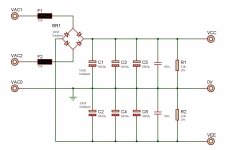
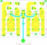
VAC1-VAC0-VAC2 are from the 35V-0-35V transformer secondaries,
All 100nf are soldered directly,
Point "A" is the centre tap directly from the transformer.
My questions,
1.) From where should I "T" off to the star ground.
2.) From where should I Tap off the +VSup and -Vsup to power the Amp Module.
There will be one "supply PCB" per channel, driven form same toroidal transformer secondaries.
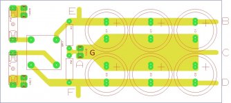
Ive labelled PCB to make things easier,
Thanks for all your guidance so far.
Still finnishing off the protection, thinking about V/I Limiting.
Now time for the supply.
Ive started the layout and have some questions, on best practice.
VAC1-VAC0-VAC2 are from the 35V-0-35V transformer secondaries,
All 100nf are soldered directly,
Point "A" is the centre tap directly from the transformer.
My questions,
1.) From where should I "T" off to the star ground.
2.) From where should I Tap off the +VSup and -Vsup to power the Amp Module.
There will be one "supply PCB" per channel, driven form same toroidal transformer secondaries.
Ive labelled PCB to make things easier,
Thanks for all your guidance so far.
Attachments
 post your amp module maybe i can help you
I'll ask the question/s differently.
Q1.) What value of fuse is required before the capacitor bank to allow reliable charging of the capacitor bank?
Q2.) How often do you intend replacing those fuses due to nuisance blowing when no fault exists?
Q3.) When you are so frustrated at how often you have to change those blown fuses, what value do you finally put in to give reliable starting over a period of a year or two?
Q4.) What protection will those enormous fuses give to your equipment/home?
Now to your questions.
The star ground should not be tee'd off the PSU. The star Ground should be located near the amplifier. It is an Audio Ground, first and foremost. Finally run a wire from the PSU to your star ground.
Tap off the amplifier supplies from the opposite ends of the PSU rails from where the rectifiers feeds in current.
Now some advice.
Twist the mains primary wires as a pair from switch to transformer.
Twist the secondary wires from each secondary to the respective rectifier.
Twist the Supply wires as a triplet from PSU to amplifier. Triplet = +ve & -ve & zero volts wires.
Twist the input flow and return wires as a pair.
Twist the speaker flow and return wires as a pair.
Thanks Guys, the circuit isnt complete,
The fuse values was just used in simulation, to kinda determine ripple at different loads, for me to understand some things more,
(no slow acting fuses in sim)
These fuses will be slow blow, and would have been resized to max rms Current (7A 500VA/(35x2)), they were only intended to protect against shorted diode in bridge, well thats was my idea anyway, Guess primary fuse will have to catch this otherwise.
The amp modules have fast acting 3A fuses on the rails, after the big caps.
Ive seen other supplies with no fuses before Bridge, and I guess for a good reason,
Ill take all the advice and learn from it,
But I didnt think about sustained pressure on fuses over time,
Thanks AndrewT
Just was asking from which point on the supply to run that wire from.
Ill also wire the rest as you advice.
Seems like "B should be V+ and D should be V- and C should be ground.
" is agreed on.
I really appreciate everyones time and advice
Warm Regards
ps, the amp module is one ive been working on for some time,
Its posted on other thread, Im hoping for the best.
http://www.diyaudio.com/forums/soli...uilding-my-own-amp-scratch-4.html#post3117148
The fuse values was just used in simulation, to kinda determine ripple at different loads, for me to understand some things more,
(no slow acting fuses in sim)
These fuses will be slow blow, and would have been resized to max rms Current (7A 500VA/(35x2)), they were only intended to protect against shorted diode in bridge, well thats was my idea anyway, Guess primary fuse will have to catch this otherwise.
The amp modules have fast acting 3A fuses on the rails, after the big caps.
Ive seen other supplies with no fuses before Bridge, and I guess for a good reason,
Ill take all the advice and learn from it,
But I didnt think about sustained pressure on fuses over time,
Thanks AndrewT
Sorry for bad wording, but this is what I meant to say to,The star ground should not be tee'd off the PSU. The star Ground should be located near the amplifier. It is an Audio Ground, first and foremost. Finally run a wire from the PSU to your star ground.
Just was asking from which point on the supply to run that wire from.
Ill also wire the rest as you advice.
Seems like "B should be V+ and D should be V- and C should be ground.
" is agreed on.
I really appreciate everyones time and advice
Warm Regards
ps, the amp module is one ive been working on for some time,
Its posted on other thread, Im hoping for the best.
http://www.diyaudio.com/forums/soli...uilding-my-own-amp-scratch-4.html#post3117148
Last edited:
The supply triplet should be connected to BCD. It would help with the twisted if B & D were extended to, right next to C. Three 1/4" spades allow a compact triplet connection.
The transformer centre tap should be connected to A.
Keep the wires from transformer to PSU as short as layout will allow, but also you must keep them twisted.
The transformer centre tap should be connected to A.
Keep the wires from transformer to PSU as short as layout will allow, but also you must keep them twisted.
If I understand you correctly, you are driving two bridges from one set of secondaries. This might create a problem: where do you connect the single CT? If you connect it to both PSU PCBs then you have two PSU grounds at slightly different potentials yet both need to be connected to the single star point so you have a ground loop. If you don't connect the CT to both PSU PCBs then things get worse because the charging currents for one PCB have to find their way there via the star ground.Vostro said:There will be one "supply PCB" per channel, driven form same toroidal transformer secondaries.
I was thinking something like this, from Mr Rod Elliott (ESP).
Star Supply grounds, then take them to Audio star.
But if its better to run both left and right amplifier from same supply board,
I can add another set of caps and change to 10 000uF EACH ?
I have plenty 6800uF 63V capacitors so I prefer them,
But 10 000uF is physically the same size.
Ill prefer to do it the best possible way I can,
So Ill wait for more comments.
Regards
Attachments

Your proposed connections appear to be different from Rod Elliot's. He has one PSU ground, in the order bridge(dirty)-cap-amp; that is fine. You have two of these, which creates the problem. You might get away with putting two lots of caps on the same board and sharing the ground bus - that way you have one dirty ground to the CT at one end and one clean ground to the audio star at the other end.
It is not the two bridges which are the problem, but two bridges often lead to poor grounding. Rod knows how to get it right, so if you copy him you will be OK.
It is not the two bridges which are the problem, but two bridges often lead to poor grounding. Rod knows how to get it right, so if you copy him you will be OK.
Hehe, I guess Im slow, I always get so so lost.
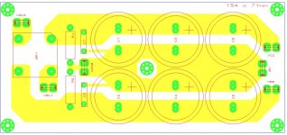
Is this Correct for Supplying Both 100W into 8R Amp Modules From the Same Supply ?
I'm Using 27200uF (4 x 6800uF 63V) per rail. (I still have about 20 of these caps left)
or possible 40000uF (4 x 10000uF 63V) per rail.
Thanks
Is this Correct for Supplying Both 100W into 8R Amp Modules From the Same Supply ?
I'm Using 27200uF (4 x 6800uF 63V) per rail. (I still have about 20 of these caps left)
or possible 40000uF (4 x 10000uF 63V) per rail.
Thanks
Attachments
continuation of previous post: 2/2
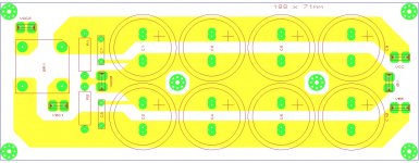
And is this a correct implimentation of Mr. Elliots diagram.
Only One transformer is used with 35V-0-35V feeding both Bridge rectifiers.
Using 20000uF (2 x 20000uF) per rail.
If not please help,
Which of the two options, this one and post above is better way to do it?
Thanks for all your patience.
And is this a correct implimentation of Mr. Elliots diagram.
Only One transformer is used with 35V-0-35V feeding both Bridge rectifiers.
Using 20000uF (2 x 20000uF) per rail.
If not please help,
Which of the two options, this one and post above is better way to do it?
Thanks for all your patience.
Attachments
Last edited:
Looking at the extra pcb space 'post 11' would take, I'm Leaning heavily to 'post10'
Only one way to see, Ill etch both amp modules, Psu from post 10 and
my small protect circuit (On/Off delay, DC detect, clipping indicator).
I must still figure out short circuit protect.
After Ive put it all together, Ill look into adding, a tone/bass/volume preamp.
Ill use the Velleman K8084 Preamp in the mean time.
Everyones continual input is greatly appreciated !
Consider connecting something like 3.3nF across the power switch.
This helps prevent arcing of the switch contacts.
Make sure you use an AC rated cap for this application.
Vishay makes some AC rated caps.
In residential house wiring, only the hot gets switched.
Yet with amp power supplies, both the Hot and Neutral get switched.
Is there a reason for switching both ?
If both poles of a switch get used for the Hot that would 1/2 the contact resistance.
Consider using a softstart with your power supply.
This helps control inrush current, makes life easier for your diodes,
Plus according to Nichicon, electrolytics don't like extreme recharge rates.
I've seen microprocessor controlled softstart circuits.
But how about 2 switches with a 12 0hm power resistor or a thermistor instead ?
Mills makes 12 ohm 50 watt wire wound resistors.
They are the ones with heat sinks that can be attached with machine screws.
Electrolytics don't like extreme discharge rates.
Even a "fast" blow fuse takes something in the order of 10ms to react.
However, transistor current limiting would take something in the order of 30ns to react.
So I suggest you have current limiting in your circuity, not only to protect your transistors and speakers,
but the electrolytics too.
.
Safety, in case the house wiring is wrong.Uunderhill said:Is there a reason for switching both ?
Safety, in case the house wiring is wrong.
Thanks for the word on this.
There are reasons why residential wiring is so heavily regulated.
Beware of buying a house renovated by a "handyman."
In North America, a little plug can be bought that has 3 lights.
Plug it in - and it shows if the Hot and Neutral are reversed - and it shows if there is a ground.
I'm wondering how power toroids are wound.
Is there an inside and outside of the primary windings ?
If so, should the Hot be connected to the inside and the Neutral be connected to the outside of the primaries ?
I looked at the Antek datasheet and it didn't say anything about this.
The Antek power toroid I have has red and black leads off the primaries.
In North America both these colours are used to indicate the Hot.
Also, toroids can be bought with electrostatic shields between the primaries and secondaries.
Think this reduces noise getting capacitively coupled to the secondaries.
Anyone tried a toroid with a shield ?
.
Ive not seen a Toroid with electrostatic shielding,
Toroids are usually wound with primary first (underneath), the secondary wound over it, on top.
There is no Live and Neutral intrinsically, as far as I know.
Of the two primary leads from the Primary, the lead you connect to Live is Live,
And the lead you connect to neutral is neutral.
Please correct me if Im incorrect !
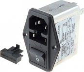
I use a similar IEC Socket to this, which breaks Live and Neautral,
But when my amp goes into standby, the microcontroller, only
controls a single relay (spst) to break the Live wire on the Amp toroid,
Keeping power on the small transformer keeping the micro in sleep,
till activated again,
Is it incorrect of me to only break Live and not neutral with the relay ?
Isolation is still achieved if IEC on/off is turned off.
But while Amp is in standby (which is most of the time,) only Live is broken.
Regards
Toroids are usually wound with primary first (underneath), the secondary wound over it, on top.
There is no Live and Neutral intrinsically, as far as I know.
Of the two primary leads from the Primary, the lead you connect to Live is Live,
And the lead you connect to neutral is neutral.
Please correct me if Im incorrect !
I use a similar IEC Socket to this, which breaks Live and Neautral,
But when my amp goes into standby, the microcontroller, only
controls a single relay (spst) to break the Live wire on the Amp toroid,
Keeping power on the small transformer keeping the micro in sleep,
till activated again,
Is it incorrect of me to only break Live and not neutral with the relay ?
Isolation is still achieved if IEC on/off is turned off.
But while Amp is in standby (which is most of the time,) only Live is broken.
Regards
Attachments
Ive not seen a Toroid with electrostatic shielding,
Toroids are usually wound with primary first (underneath), the secondary wound over it, on top.
There is no Live and Neutral intrinsically, as far as I know.
Of the two primary leads from the Primary, the lead you connect to Live is Live,
And the lead you connect to neutral is neutral.
Plitron make isolation toroids with electrostatic (Faraday) shields.
Antek sell step down toroids and an option (for more money) is an electrostatic shield between the primaries and secondaries.
From what I have read, the primaries and secondaries of a toroid are
highly coupled together - this can be a fault of toroid.
Do you have a softstart ? If not I highly recommend using one.
Also, under high loads, I would imagine the diodes radiate quite the EMR spectrum inside the case.
I've read its important to keep the secondary, diode and first cap lead lengths short for this reason.
Also, I think its not just the amount of ripple on the supply rails that's important,
but also, the frequency spectrum on the ripple - caused by diode switching.
For this reason, have you considered C-R-C or C-L-C ?
.
- Status
- This old topic is closed. If you want to reopen this topic, contact a moderator using the "Report Post" button.
- Home
- Amplifiers
- Solid State
- More Supply Questions