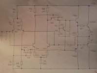
Been fixing a car amplifier and decided to draw out the circuit,
But I'm only used to Vas as common emitter, but from this circuit
looks like Q305, Q302 are common base.
Can anyone comment and how does this compare to "normal" Vas amps
The problem on the amp was the supply section and not the amp,
I just redrew the amp section to learn more.
Reagards
But I'm only used to Vas as common emitter, but from this circuit
looks like Q305, Q302 are common base.
Can anyone comment and how does this compare to "normal" Vas amps
The problem on the amp was the supply section and not the amp,
I just redrew the amp section to learn more.
Reagards
Attachments
Here you find circuits like that :A Paul Kemble web page - Symmetrical PA designs.
")
Here is the grand father :http://www.marklev.com/JC3/jc3schematics.jpg
Actually the Vas is driven from the base AND from the emitter.
Actually the Vas is driven from the base AND from the emitter.
Advantages of common base VAS
HI,
If one would compare the VAS used in the picture in post #1 with a standard VAS (base connnected to LTP, emmiter with series R to rail).
What would be the advantages/disadvantages of the common base VAS?
I simulated two amp, both are identical except for the VAS, one is standard the other is common base.
==> everything I can simulate is approx the same!?
The drive provided to the VAS emitters/non inverting inputs
by the differentials non inverting outputs is negligible compared
to the drive that go from inverting output of the differentials to
the VAS bases/inverting inputs , this latter path has way higher OLG ,
so the VAS transistors works as classical common emitters , the cascoding
being only apparent but not effective at all in respect to perfs differences...
A re drawn picture :
Attachments
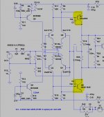
Thanks for the feedback Wahab!
I was expecting this answer, it's good to know that I was thinking wright. However I'm not managing to get this higher OLG.
Have a look at the circuit (common base VAS) => OLG is 50dB.
If I make it standard VAS, with same VAS current, I'm getting identical OLG of 50dB.
The two resistors (R17+R6) are determing the VAS idle current but also the OLG gain. This means that with same VAS current in common base, or standard VAS, the OLG will be the same, not?
Greetz
Attachments
Hi Guys
This interface between the input diff and the VAS is always described as a "folded cascode", but this description does not apply in all cases.
For this to truly be a folded cascode, the VAS base has to be at AC ground. You can do this easily by shunting the base to the supply with a cap, or by tying the base to a fixed voltage - often a LED or diode string. Driving the VAS emitter from the input side of the diff amp produces an overall signal inversion that must be corrected to have a noninverting amplifier overall. The current through the VAS can never be more than half the current of the diff amp.
Obviously, if the VAS emitter is at AC ground, it is a standard common-emitter stage with lots of voltage gain and present the corrective signal inversion for overall noninverting output.
The connection drawn above has the appearance of push-pull drive of the BE junction of the VAS, but in fact this is not the case. Curl and Pass have both used this connection but never really explained why, so copies of this ripple through a small number of hobbyist and pro amplifier builds. Thagard described the "folded cascode" as making the stages look like one, reducing overall gain but potentially increasing speed due to the cascode... but... it is only a cascode if the VAS base is essentially undriven. If you simulate the circuit with a cap across R17 you will see what the extreme of performance is and will likely stay with the standard connection.
Have fun
Kevin O'Connor
londonpower.com
- Status
- This old topic is closed. If you want to reopen this topic, contact a moderator using the "Report Post" button.
- Home
- Amplifiers
- Solid State
- Common Base Vas ?