Headphone amplfier
The headphone amplifier design is my own, it's a nice relatively simple circuit (could be made simpler with a bootstrap, but I hate the idea of bootstrapping and would suffer from it). It performs nicely as a headphone amp and drives my SR-325is very well") . I've made my headphone matching resistor values low for the amplifier described in this thread because I believe damping factor really matters for headphones.
. I've made my headphone matching resistor values low for the amplifier described in this thread because I believe damping factor really matters for headphones.
I usually design around a tight budget with a good deal of time to think about the design before I build it, usually a couple of months. Although there's little evidence here, most of the stuff I build uses a split supply!
I'm not really too keen on spending money on a cheap amplifier, I've pulled a fair few apart in the past few years and found many horror stories inside them (AMSTRAD are the worst), using chip amplifiers with up to 15% THD sometimes, if you don't believe me then Google the datasheet for TA8207K, almost half of all the stuff I've butchered uses it! It's partly because of this that I'm going to build my own.
Regarding student life, I'm not really much of a boozer, I certainly wouldn't be getting drunk for the hell of it . All you are really paying for is a hangover, and in London, the cost of living is high enough already!
The headphone amplifier design is my own, it's a nice relatively simple circuit (could be made simpler with a bootstrap, but I hate the idea of bootstrapping and would suffer from it). It performs nicely as a headphone amp and drives my SR-325is very well
. I've made my headphone matching resistor values low for the amplifier described in this thread because I believe damping factor really matters for headphones.I usually design around a tight budget with a good deal of time to think about the design before I build it, usually a couple of months. Although there's little evidence here, most of the stuff I build uses a split supply
!I'm not really too keen on spending money on a cheap amplifier, I've pulled a fair few apart in the past few years and found many horror stories inside them (AMSTRAD are the worst), using chip amplifiers with up to 15% THD sometimes
, if you don't believe me then Google the datasheet for TA8207K, almost half of all the stuff I've butchered uses it! It's partly because of this that I'm going to build my own.Regarding student life, I'm not really much of a boozer, I certainly wouldn't be getting drunk for the hell of it
. All you are really paying for is a hangover, and in London, the cost of living is high enough already!more cool than a chip amp, mostly as you designed it
I am pleased you have had much success with the headphone amplifier. It reminds me of the JLH with a few extra stages. I would be curious to hear if you have compared them, is your design lower distortion with simulation?
I think capacitor coupled output stages have an unreasonably bad name. Yes they do usually define the bass response cutoff, and reduce damping, but they save costs, no speaker protection is needed, and also the power supply is simpler. In practice (after having played with a lot of other peoples amp designs) I am not convinced that capacitor coupled output stages should be avoided.
A quick google came up with more HiFi chip amps the LM1875 "Low distortion: 0.015%, 1 kHz, 20 W" and might just match your transformer:
Better chip amps look like they exist such as the LME49810, but I am not sure they can work with your transformer. All I am trying to say is its a practical HiFi idea, and not all are as bad as a TA8207K.
That said:
Yes and with this requirement I think you should just build your amplifier design, as its definitely more cool than a chip amp, mostly as you designed it.
I am no expert on amplifier design, but I suspect that power supply modulation on class AB amplifiers with your proposed design can be a serious issue.
Do you have any regulators in your box of bits?
Do you have enough to regulate the power separately for the low power and high power parts of the circuit?
Would be interesting if these reduced distortion at full load at 50 Hz, on your osciliscope.
Will you be using a PCB, Strip board, Turrets?
I was not much of a boozer before university, but while at university I made a thermostatic control for a kettle heating element to extract sugar from grain, I made British "real ale" better than I could buy at any price, though some micro breweries get very close. With barrels, I needed to drink 40 pints in 3-4 days, but help was at hand, and it was lots of fun, and not just the drinking
The headphone amplifier design is my own, it's a nice relatively simple circuit (could be made simpler with a bootstrap, but I hate the idea of bootstrapping and would suffer from it). It performs nicely as a headphone amp and drives my SR-325is very well
I am pleased you have had much success with the headphone amplifier. It reminds me of the JLH with a few extra stages. I would be curious to hear if you have compared them, is your design lower distortion with simulation?
I usually design around a tight budget with a good deal of time to think about the design before I build it, usually a couple of months. Although there's little evidence here, most of the stuff I build uses a split supply
I think capacitor coupled output stages have an unreasonably bad name. Yes they do usually define the bass response cutoff, and reduce damping, but they save costs, no speaker protection is needed, and also the power supply is simpler. In practice (after having played with a lot of other peoples amp designs) I am not convinced that capacitor coupled output stages should be avoided.
I'm not really too keen on spending money on a cheap amplifier, I've pulled a fair few apart in the past few years and found many horror stories inside them (AMSTRAD are the worst), using chip amplifiers with up to 15% THD sometimes
A quick google came up with more HiFi chip amps the LM1875 "Low distortion: 0.015%, 1 kHz, 20 W" and might just match your transformer:
The amplifier must use my 16.5V transformer (it looks and feels at least 30VA, picture attached with CD for comparison, measures 50x60x55 excluding pins).
Better chip amps look like they exist such as the LME49810, but I am not sure they can work with your transformer. All I am trying to say is its a practical HiFi idea, and not all are as bad as a TA8207K.
That said:
To impress people on my course with my design and build (especially build) skills.
Yes and with this requirement I think you should just build your amplifier design, as its definitely more cool than a chip amp, mostly as you designed it.
I am no expert on amplifier design, but I suspect that power supply modulation on class AB amplifiers with your proposed design can be a serious issue.
Do you have any regulators in your box of bits?
Do you have enough to regulate the power separately for the low power and high power parts of the circuit?
Would be interesting if these reduced distortion at full load at 50 Hz, on your osciliscope.
Will you be using a PCB, Strip board, Turrets?
Regarding student life, I'm not really much of a boozer, I certainly wouldn't be getting drunk for the hell of it
I was not much of a boozer before university, but while at university I made a thermostatic control for a kettle heating element to extract sugar from grain, I made British "real ale" better than I could buy at any price, though some micro breweries get very close. With barrels, I needed to drink 40 pints in 3-4 days, but help was at hand, and it was lots of fun, and not just the drinking
This design idea should do it http://www.diyaudio.com/forums/atta...lithic-supersymmetry-current-feedback-cfx.gif http://www.diyaudio.com/forums/pass-labs/11205-monolithic-supersymmetry-current-feedback.htmlFirst off I'm not going to spend a single penny buying parts for this amplifier, all of the parts featured in the design are those that I already have, and the design is optimised to use up as much space-hogging stuff that I have lying around as possible!
So, here's my revised brief in order of priority:
- The amplifier must use parts I already have, lots of em
Dual rails are not mandatory (floating output also works with single supply), a phase splitter is easy to build and if you succeed, it will be a proof of your skills in this field.
BTW, in the schematic diagram of your headphone-amp, 2.7V on both ends of R13 cannot be correct.
Last edited:
There's nothing wrong with my Headphone Amplifier!
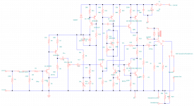
Firstly, the headphone amplifier works perfectly, I think you have misinterpreted the schematic which revolves around using the JFET's cut-off voltage to set the output bias with 2.7V @ about 130uA the output offset is 10.2V, the voltage across R3 is 7.5 volts, if it didn't work then I would know about it now after having got a good 30 hours or so of listening out of it.
I haven't based the headphone amp around anything other than necessity and simplicity of design, part of the fun was trying to see how simple I could keep it while still maintaining good performance. The I haven't seen the JLH up until you mentioned it, it just looks like the standard Class A circuit used in Rod Elliots DoZ amplifier but for headphone, (it's probably where he nicked the idea from in the first place ). Regarding distortion, I couldn't really measure any (I can't measure accurately below about 0.02% THD with what I've got) and I went all the way from 100Hz-10KHz without seeing any signs harmonics on the FFT of my cheap mini oscilloscope  , so it's all good (I used a DacMagic with test tones from audacity as the signal source and a high quality A-D to record back into audacity and notch out the test tones, yes I know it's not very professional ) I tested THD at 100mW into a 33ohm resistor, 1.8V RMS. With a capacitively coupled output stage damping factor is about 15 with a 32ohm load which is quite good when compared to some other headphone amps. At 500Hz it's about 120. A capacitively coupled output can certainly eliminate the extra effort needed for a split supply, and with a self biased input stage, whats not to like .
Unfortunately it's not economical to have such a high time constant in the amplifier I'm currently building (I don't have any 6800uF caps anyway), but for my small speakers which don't go that low in the first place, it's acceptable, with a damping factor of 10.6 at their LF cut-off which will increase all the way to about 100 or more as frequency increases, it's perfectly acceptable. For small amplifiers it can be a good idea, but for larger ones where low frequency damping is important (as well as ripple current), split supply is the only sensible way to go.
Regarding chip amps, there are some really good devices out there, I was referring to the poor chip amps found in some low quality 'hifi' equipment that have such awful performance. I've built a couple of power amps using LM3875 in my time and they sounded excellent.
I do have regulators LM350K LM317 and LM7812 but with a regulated supply, power output is diminished (which is one of the main points in my brief), and I can't really fit more than 4 devices on my heatsink. The input stage already has a discrete shunt regulator ( see Q3 Q4 and D2) that will keep rejection low as the input stage has low open loop gain. Also because the power amplifier has a relatively low closed loop gain and a very high open loop gain, power supply rejection will be excellent (at least 80dB) and careful attention has been payed to keeping the ground buss as clean as possible, making sure the current running through it is constant by using a shunt regulator, and also ensuring that the current running through the power amplifier stage is not affected by power supply voltage. Don't worry, I know how to ground properly!
I will be building the amplifier on strip board, with a doubled up (with single core wire soldered between tracks) ground buss and symmetrical stereo layout. The input stage will use 2.5mm stripboard and the output stage will use 3.8mm stripboard (with soldered over tracks for extra current capacity) switching over to 3.8mm between the VAS and output stages. I will of course be using extra thick cable for the ground. The power supply and muting circuit will be on 3.8mm stripboard.
Firstly, the headphone amplifier works perfectly, I think you have misinterpreted the schematic which revolves around using the JFET's cut-off voltage to set the output bias with 2.7V @ about 130uA the output offset is 10.2V, the voltage across R3 is 7.5 volts, if it didn't work then I would know about it now after having got a good 30 hours or so of listening out of it
.I haven't based the headphone amp around anything other than necessity and simplicity of design, part of the fun was trying to see how simple I could keep it while still maintaining good performance
. The I haven't seen the JLH up until you mentioned it, it just looks like the standard Class A circuit used in Rod Elliots DoZ amplifier but for headphone, (it's probably where he nicked the idea from in the first place ). Regarding distortion, I couldn't really measure any (I can't measure accurately below about 0.02% THD with what I've got) and I went all the way from 100Hz-10KHz without seeing any signs harmonics on the FFT of my cheap mini oscilloscope , so it's all good (I used a DacMagic with test tones from audacity as the signal source and a high quality A-D to record back into audacity and notch out the test tones, yes I know it's not very professional ) I tested THD at 100mW into a 33ohm resistor, 1.8V RMS. With a capacitively coupled output stage damping factor is about 15 with a 32ohm load which is quite good when compared to some other headphone amps. At 500Hz it's about 120. A capacitively coupled output can certainly eliminate the extra effort needed for a split supply, and with a self biased input stage, whats not to like .Unfortunately it's not economical to have such a high time constant in the amplifier I'm currently building (I don't have any 6800uF caps anyway), but for my small speakers which don't go that low in the first place, it's acceptable, with a damping factor of 10.6 at their LF cut-off which will increase all the way to about 100 or more as frequency increases, it's perfectly acceptable. For small amplifiers it can be a good idea, but for larger ones where low frequency damping is important (as well as ripple current), split supply is the only sensible way to go.
Regarding chip amps, there are some really good devices out there, I was referring to the poor chip amps found in some low quality 'hifi' equipment that have such awful performance. I've built a couple of power amps using LM3875 in my time and they sounded excellent
. I do have regulators LM350K LM317 and LM7812 but with a regulated supply, power output is diminished (which is one of the main points in my brief), and I can't really fit more than 4 devices on my heatsink. The input stage already has a discrete shunt regulator ( see Q3 Q4 and D2) that will keep rejection low as the input stage has low open loop gain. Also because the power amplifier has a relatively low closed loop gain and a very high open loop gain, power supply rejection will be excellent (at least 80dB) and careful attention has been payed to keeping the ground buss as clean as possible, making sure the current running through it is constant by using a shunt regulator, and also ensuring that the current running through the power amplifier stage is not affected by power supply voltage. Don't worry, I know how to ground properly
!I will be building the amplifier on strip board, with a doubled up (with single core wire soldered between tracks) ground buss and symmetrical stereo layout. The input stage will use 2.5mm stripboard and the output stage will use 3.8mm stripboard (with soldered over tracks for extra current capacity) switching over to 3.8mm between the VAS and output stages. I will of course be using extra thick cable for the ground. The power supply and muting circuit will be on 3.8mm stripboard.
I built ultrasmall amp based on two LT1210's, inverted, unity gain, p2p on heatsink, and small dual SOIC opamp board from Texas Instruments is big enough to cover the "power section". I guess I am taking it to uni for first week to see if it is a good idea to bring over my huge class A amp.
(Photoed with toaster)
Heatsink is small, but does the job really fine. I just need some RCA plugs.
I also built LM1875 based amp, with pushbutton volume control.
I am not good with making cases for amps,but you might DIY em
An externally hosted image should be here but it was not working when we last tested it.
An externally hosted image should be here but it was not working when we last tested it.
(Photoed with toaster)
Heatsink is small, but does the job really fine. I just need some RCA plugs.
I also built LM1875 based amp, with pushbutton volume control.
An externally hosted image should be here but it was not working when we last tested it.
An externally hosted image should be here but it was not working when we last tested it.
I am not good with making cases for amps,but you might DIY em
hey monty78pig I have done similar exercises to yourself in the past (building amps out of what's lying around. I have just finished a masters in Electronic and Electrical engineering at Imperial so I understand that the current UK student life isn't very party orientated. For compressed music (virtually everything modern) low power is fine. When in halls no one had anything better than an ipod dock so even with only a 30+30W amplifier and mission audio speakers I was the guy to go to.
I had a very quick look at your speaker amplifier schematic and would like to ask you why you didn't go with a long tailed pair for the input instead of the jfet buffer and then feedback to Q5? higher stable open loop gain?
my current setup is uses four channels of amplification with a mini-dsp. I managed to fit this into a 350mmx100mmx250mm box so I wouldn't give up on the multi amplifier dream.
Updates!
Hi kipman725, I designed the amplifier with single supply in mind as the transformer I have has only one output winding. An LTP in this application would require a virtual earth, and the output DC bias couldn't be adjusted (easily, that is). The JFET/PNP combo on the input is useful because it is self biasing, I don't have to use a bias network (which I have never liked using) and gives me 10dB of gain before the attenuator stage. This gives me a lower noise floor. It also allows me to decrease the closed loop gain of the power amp stage so gives another 10dB of supply rail rejection and lower distortion (I'm rather neurotic when it comes to PSRR ). Another advantage is the stability, which should be exceptional, I don't have the time at the moment to chase parasitic oscillations! I also quite like the idea of current feedback amplifiers, and this application is perfect for them.
I've got my place at uni (Brunel) and am halfway through constructing the amp. The low power does not bother me as I'll soon be replacing the Gales with some nice 93dB/W Fostex FE126EN bass reflex speakers. As opposed to the gales which are around 90dB/W, which will effectively double my output power for free. Lots of people seem to forget efficiency when looking for maximum sound output. I'll be using full range in future for all my stuff, so won't need to bother with active crossovers and multiple amps. Are you using the DSP for active crossover/phase correction? I'll be planning my enclosure layout fairly carefully.
Over the years I've collected lots of pre 'loudness war' CDs that sound excellent, but I tend to listen at lower levels and using headphones (which is what this amp will mostly be used for). Even if clipping occurs at this power level then hopefully it won't be enough to kill the tweeters...
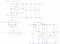
I've made a few modifications to the schematic (mostly safety measures such as making sure that if the pot in the VBE multiplier goes open circuit then the amp won't go into insane bias mode and kill the output transistors). I've also changed the regulator on the muting circuit to a discrete one, partly to use up components and partly for the (somewhat perverse) satisfaction of an all discrete design .
.
Hi kipman725, I designed the amplifier with single supply in mind as the transformer I have has only one output winding. An LTP in this application would require a virtual earth, and the output DC bias couldn't be adjusted (easily, that is
). The JFET/PNP combo on the input is useful because it is self biasing, I don't have to use a bias network (which I have never liked using) and gives me 10dB of gain before the attenuator stage. This gives me a lower noise floor. It also allows me to decrease the closed loop gain of the power amp stage so gives another 10dB of supply rail rejection and lower distortion (I'm rather neurotic when it comes to PSRR ). Another advantage is the stability, which should be exceptional, I don't have the time at the moment to chase parasitic oscillations! I also quite like the idea of current feedback amplifiers, and this application is perfect for them.I've got my place at uni
(Brunel) and am halfway through constructing the amp. The low power does not bother me as I'll soon be replacing the Gales with some nice 93dB/W Fostex FE126EN bass reflex speakers. As opposed to the gales which are around 90dB/W, which will effectively double my output power for free. Lots of people seem to forget efficiency when looking for maximum sound output. I'll be using full range in future for all my stuff, so won't need to bother with active crossovers and multiple amps. Are you using the DSP for active crossover/phase correction? I'll be planning my enclosure layout fairly carefully.Over the years I've collected lots of pre 'loudness war' CDs that sound excellent, but I tend to listen at lower levels and using headphones (which is what this amp will mostly be used for). Even if clipping occurs at this power level then hopefully it won't be enough to kill the tweeters...
I've made a few modifications to the schematic (mostly safety measures such as making sure that if the pot in the VBE multiplier goes open circuit then the amp won't go into insane bias mode and kill the output transistors). I've also changed the regulator on the muting circuit to a discrete one, partly to use up components and partly for the (somewhat perverse) satisfaction of an all discrete design
.Attachments
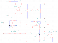
 . I've got tons of 5V6 zeners so will use one of those. (Amended schematic attached).
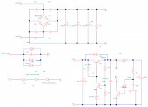
5V6 + 1Vbe isn't that bad. It's not far away from a 1N821's structure. 6V2 or 6V8 would be closer. The Vbe changes due to temperature and emitter current changes (!) are "hidden" by the zener voltage. In this particular case, a perfect compensation isn't needed.
If you want to include the output capacitor inside the feedback loop, here is an example on how to do it 4QD-TEC: Low distortion Audio amplifier
If you want to include the output capacitor inside the feedback loop, here is an example on how to do it 4QD-TEC: Low distortion Audio amplifier
- Status
- This old topic is closed. If you want to reopen this topic, contact a moderator using the "Report Post" button.
- Home
- Amplifiers
- Solid State
- An amplifier to take to University - A small low power integrated amplifier