Wouldn't you need more than 4 pr for 2 ohm operation at that power output ...?
My simulation tells me that 4 pr should be enough.
Those output transistors have derate factor 1.43 above 25 degree C. If expected 90 degree C of the junction temperature then 200 W derated by 1.43*65 and this gives 107 W. With good heat sink it should be possible to drive 2 ohm at full power. Look post #13 for disipated power per output transistor.
dado
power/voltage drops from 200W into 8r0 to 375W into 4r0, i.e. -0.56dBW
and drops from 375W to 701W into 3r0, i.e. -0.59dBW.
These two drops seems surprisingly close.
I would expect the drop into 4r0 to be much less than the drop into 2r0.
How did you measure these output figures?
Were the mains supply voltages the same? Did you meausre the mains supply voltages for all three output power measurements?
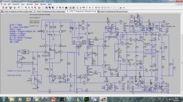
Those results are simulated only. I suppose that the drop for real amp will be bigger, depends of used transformer. I used serial resistor in both power lines, but actually I don't have real power supply internal resistance.
Here is schematic as I used for the simulation.
dado
Attachments
2r0 loading is an easy load for a 4ohm rated amplifier.
I would expect every 4ohm rated amplifier to be able to drive a 2r0 test load without any difficulty. The only problem would be extended testing raising the heatsink temperature above the design target limit.
If you need a 2ohm rated amplifier, then it must be able to drive a 1r0 test load and preferably lower.
Yes, true , but ....and this is real world application , not Google design, for 4 pr to dissipate 700+ rms @ 2 ohm we may see an issue with SOA temps and reliability. Sonics tend to take a back seat too , thermal tracking and ting ...
Just saying .....

My simulation tells me that 4 pr should be enough.
Those output transistors have derate factor 1.43 above 25 degree C. If expected 90 degree C of the junction temperature then 200 W derated by 1.43*65 and this gives 107 W. With good heat sink it should be possible to drive 2 ohm at full power. Look post #13 for disipated power per output transistor.
dado
Me tinks at 700+ watts this could be an issue ........

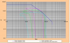
I've done a quick SOAR calculation for 4pairs 1302/3281. I used the 1second SOAR curve from the datasheet
65V output peak:
- 190Wrms / 55° phase angle / 8R
- 300Wrms / 45° phase angle / 4R
- 410Wrms /35° phase anlge /2R
OPS is running at max 50°C
==> 4 pairs is NOT sufficiënt, see picture below
==> 5 pairs is on the edge, I would use 6 pairs.
Greetz
65V output peak:
- 190Wrms / 55° phase angle / 8R
- 300Wrms / 45° phase angle / 4R
- 410Wrms /35° phase anlge /2R
OPS is running at max 50°C
==> 4 pairs is NOT sufficiënt, see picture below
==> 5 pairs is on the edge, I would use 6 pairs.
Greetz
Attachments
I've done a quick SOAR calculation for 4pairs 1302/3281. I used the 1second SOAR curve from the datasheet
65V output peak:
- 190Wrms / 55° phase angle / 8R
- 300Wrms / 45° phase angle / 4R
- 410Wrms /35° phase anlge /2R
OPS is running at max 50°C
==> 4 pairs is NOT sufficiënt, see picture below
==> 5 pairs is on the edge, I would use 6 pairs.
Greetz
65 V is the Capacitance multiplier input, then you should drop it to 57 V after C multiplier.
There is Backer clamp too defining max output volatage peak and it is 54 V. I showed power dissipation on C multiplier transistor too(there are 6 pairs actually if you count C multplier power transistors).
dado
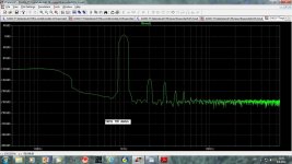
Now be prepared for something special.
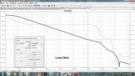
ULGF = 1.3MHz
RL = 4ohm, Pout=330W
THD1k = 7ppb
THD20k = 1.33ppm (1.08ppm, RL = 8ohm)
THD50k = 15.72ppm
THD100k =0.009624%
THD200k =0.061653%
RL = 4k, THD20k = 0.77ppm
PM = 61 degree
GM = 15dB
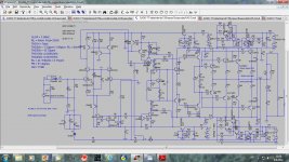
Those are simulated result for a bit different schematic, VAS is now Hawksford enhanced cascode. Some resistors are changed(LTP emitter resistors) and TMC is standard not bridged. Distortion figure are better a bit only(much better at 100kHz) but the stability is much better. I used beta enhanced VAS in first schematic because I implemented in my working TT amp http://www.diyaudio.com/forums/solid-state/182554-thermaltrak-tmc-amp-5.html#post2856550 and it works really good. I tried to use before Hawksford enhanced cascoded VAS but it simulated the same as beta enhanced VAS and it needs some headroom to work. Now I use higher voltage in input stage then in OPS, so some voltage lose is no problem.
Included schematic, 1kHz FFT and Loop Gain screen shots.
I have simulated low power simpler version and I will show it soon.
dado
ULGF = 1.3MHz
RL = 4ohm, Pout=330W
THD1k = 7ppb
THD20k = 1.33ppm (1.08ppm, RL = 8ohm)
THD50k = 15.72ppm
THD100k =0.009624%
THD200k =0.061653%
RL = 4k, THD20k = 0.77ppm
PM = 61 degree
GM = 15dB
Those are simulated result for a bit different schematic, VAS is now Hawksford enhanced cascode. Some resistors are changed(LTP emitter resistors) and TMC is standard not bridged. Distortion figure are better a bit only(much better at 100kHz) but the stability is much better. I used beta enhanced VAS in first schematic because I implemented in my working TT amp http://www.diyaudio.com/forums/solid-state/182554-thermaltrak-tmc-amp-5.html#post2856550 and it works really good. I tried to use before Hawksford enhanced cascoded VAS but it simulated the same as beta enhanced VAS and it needs some headroom to work. Now I use higher voltage in input stage then in OPS, so some voltage lose is no problem.
Included schematic, 1kHz FFT and Loop Gain screen shots.
I have simulated low power simpler version and I will show it soon.
dado
Attachments
Hi D,
The loop gain plots show PM @ 87°.
Yet you quote PM=61° in your post.
Why does this difference in values occur?
The plots show (in my very ill informed view) that the 0db cross could be pushed out to ~ 2MHz and still maintain good phase margin. Would it be possible to investigate this in your simulation?
R81 located between Q18 & Q16 seems odd.
Last edited:
Hi D,
The loop gain plots show PM @ 87°.
Yet you quote PM=61° in your post.
Why does this difference in values occur?
The plots show (in my very ill informed view) that the 0db cross could be pushed out to ~ 2MHz and still maintain good phase margin. Would it be possible to investigate this in your simulation?
R81 located between Q18 & Q16 seems odd.
Phase Margin is difference between 180 degree and the phase shift showen, means 180-87.5= 92.5degree.
I forgot to remove R81, left from some test.
Here is the schematic.
dado
Attachments
Hi Dado
Nice work.
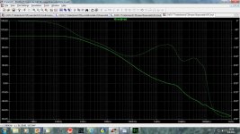
I am a bit surprised by the loop gain plot. After heated debate in earlier threads I think that finally there was consensus that TMC is a second order system and that the similarity to (1st order) Miller comp in the outer loop is deceptive. The loop gain plot that sets the stability limit should show second order behaviour and I don't see that.
Is there some explanation?
Best wishes
David
Nice work.
I am a bit surprised by the loop gain plot. After heated debate in earlier threads I think that finally there was consensus that TMC is a second order system and that the similarity to (1st order) Miller comp in the outer loop is deceptive. The loop gain plot that sets the stability limit should show second order behaviour and I don't see that.
Is there some explanation?
Best wishes
David
Hi Dado
Nice work.
I am a bit surprised by the loop gain plot. After heated debate in earlier threads I think that finally there was consensus that TMC is a second order system and that the similarity to (1st order) Miller comp in the outer loop is deceptive. The loop gain plot that sets the stability limit should show second order behaviour and I don't see that.
Is there some explanation?
Best wishes
David
It is similar to Miller comp if TMC resistor was connected outside(directly to output) the probe. Here is screen shot with the resistor inside the probe.
Thanks for your comment.
dado
Attachments
Here is low power version.
ULGF = 1MHz
RL = 8ohm, Pout=95W
THD1k = 1.09ppm
THD20k = 1.74ppm
THD50k = 16.15ppm
THD100k =0.014506%
THD200k =0.114467%
RL = 4k, THD20k = 0.77ppm
PM = 90 degree
GM = 15dB
It is quite simple, specialy if capacitance multipliers for OPS were removed and powered with +-45 V instead.
dado
ULGF = 1MHz
RL = 8ohm, Pout=95W
THD1k = 1.09ppm
THD20k = 1.74ppm
THD50k = 16.15ppm
THD100k =0.014506%
THD200k =0.114467%
RL = 4k, THD20k = 0.77ppm
PM = 90 degree
GM = 15dB
It is quite simple, specialy if capacitance multipliers for OPS were removed and powered with +-45 V instead.
dado
Attachments
what is a C multiplier?
Capacitance multiplier - Transistor connected to a capacitor to "multiply" the effective capacitance.
Best wishes
David
It what kind of application is that used? You get the the nonlinearity and limitations of the transistor for free as bonus.Capacitance multiplier - Transistor connected to a capacitor to "multiply" the effective capacitance.
Best wishes
David
and why not just use a bigger C instead of a C multiplier?
You can search this forum, it was written quite a lot about capacitance multiplier here.
- Status
- This old topic is closed. If you want to reopen this topic, contact a moderator using the "Report Post" button.
- Home
- Amplifiers
- Solid State
- TT amp, 200W/8ohm, 701W/2ohm