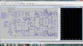
Here is my attempt to construct more powerful amp:
200W on 8ohm load
375W on 4ohm load
701W on 2ohm load
This amps is combination of ThermalTrak and standard ONSEMI power transistors. OPS is a Triple containing two TT pairs and two standard power transistors of the same family. As the power supply is of the same importance (maybe even more) as the amp itself I used Capacitance multiplier situated close to the OPS and the input stage. Input stage and OPS could be powered from different main power supply or from the same one. To facilitate use of the Baker clam input stage capacitance multiplier has 4 to 5V higher output then the OPS’s capacitance multiplier. As a bonus OPS’s capacitance multiplier contains a loudspeaker protection circuitry.
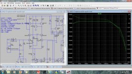
Those are simulated results:
ULGF = 1.3MHz
RL = 4ohm, Pout=320W
THD1k = 2ppb
THD20k = 0.96ppm (0.90ppm, RL = 8ohm)
THD50k = 13.42ppm
THD100k = 0.014%
RL = 4k, THD20k = 0.81ppm
PM = 61 degree
GM = 15dB
The main goal is to have very short connection between OPS and dedicated power supply. The amp circuitry is quite close to may previous TT amp, and that one plays music for some moths with no problem at all and nicely too.
200W on 8ohm load
375W on 4ohm load
701W on 2ohm load
This amps is combination of ThermalTrak and standard ONSEMI power transistors. OPS is a Triple containing two TT pairs and two standard power transistors of the same family. As the power supply is of the same importance (maybe even more) as the amp itself I used Capacitance multiplier situated close to the OPS and the input stage. Input stage and OPS could be powered from different main power supply or from the same one. To facilitate use of the Baker clam input stage capacitance multiplier has 4 to 5V higher output then the OPS’s capacitance multiplier. As a bonus OPS’s capacitance multiplier contains a loudspeaker protection circuitry.
Those are simulated results:
ULGF = 1.3MHz
RL = 4ohm, Pout=320W
THD1k = 2ppb
THD20k = 0.96ppm (0.90ppm, RL = 8ohm)
THD50k = 13.42ppm
THD100k = 0.014%
RL = 4k, THD20k = 0.81ppm
PM = 61 degree
GM = 15dB
The main goal is to have very short connection between OPS and dedicated power supply. The amp circuitry is quite close to may previous TT amp, and that one plays music for some moths with no problem at all and nicely too.
Attachments

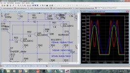
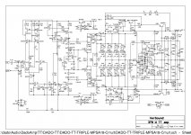
Here is OPS’s C multiplier with the loudspeaker protection. On the main amp schematic OPS’s C multiplier was simplified with no loudspeaker protection shown.
No PCB design was not atempted yet.
dado
No PCB design was not atempted yet.
dado
Attachments

Cool to see more people go to greath lengths and detail to create their own pet amp. Good numbers too! Almost sounds like you had a peek at the Power Supply Reservoir Size thread too ")
Are you close to actual prototype creation or you still have to make the real schematic? (I don't regard simulation schematics the real schematic, so much is omitted ususally)
Edit: Your capacitance multipliers look very interesting; mind you if I would try to incorporate it in my design and see what results it yields?
Last edited:
Nothing is omitted here(except main power supply with big caps, similar as I used in my other TT thread) and my actual firs TT amp is very close to the simulation stability wise, distortion was not measured as I don’t have the tool yet(planning to use PC and good sound card but always something else is more important).
Nice, in my schematic there are some parts omitted, most notably decoupling / reservoir caps onboard. When it comes to distortion measurements I was in the same boat as you. I did some research into audio analyzer software and one remarkable piece came out of it: Virtins' Multi-Instrument.
It's not free, it does its job very well (including soundcard calibration and native distortion cancelling) and yields pretty accurate results when used with a decent soundcard. I used the ASIO4ALL driver as the soundcard interface for the tool. I used it to measure MF80, my 80-watts 4Ohm amp, yielding a 10K THD of around 0.00017%. Don't mind the increasing distortion the lower the frequency, the amp has now a big enough feedback cap
Note: When I tried MI, it was rather buggy, so that may be prohibitive to actually buying it for the price ($100 back then)
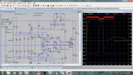
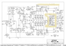
After extensive simulation here is the schematic, I think, to be used in practical implementation of this amp.
The distortion at 20kHz and 320W/4ohm is now a bit higher, risen from 0.96 ppm to 1.4 ppm but it is more stable now. During the power simulation I noticed a small oscillation at 3MHz. That was solved with R77, C33 and R78, C34 added between the drivers and output transistors in the power lines.
Combinations of the output transistors could be used for different output power and different power supply voltage.
Full power 350W/4ohm and +- 65 V of the power supply: NJL3282/1302 and MJL3281/1302
Lower power 230W/4ohm and +-55 V of the power supply: NJL0281/0302 and MJL0281/0302 (or MJW0281/0302)
I expect that lower power version could sound a bit better as suggested output transistors have lower Cob of 400pF compared with 600pF of the higher power version.
dado
Attachments
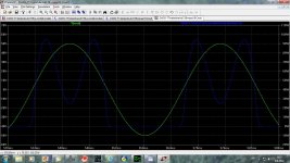
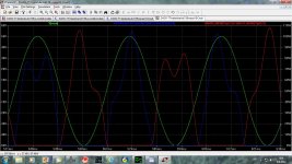
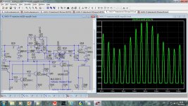
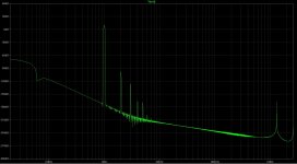
This is FFT at 15 W and 315 W on 4 ohm respectively.
dado
Hi Dadod,
I always have a look at your threads when something new is posted.
Your amps are looking very well designed. And to be honest, a bit to complex for me.
Your FFT's are looking very good, but most people here are using the the "Blackman" windowing function when showing the FFT.
Can you perform the FFT's again with the "Blackman" selected?
I use them as reference.
Greetz
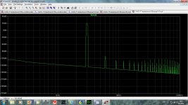
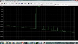
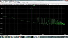
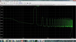
Here are the Blackman FFTs.
Actually it is not so complex, you can skip Loudspeaker ptotection if you don't like this type of the protection(circled).
dado
Attachments
I don't have the experience yet to make the corrolation between FFT simulation and my hearing.
My last amp: http://www.diyaudio.com/forums/solid-state/198209-amp-design-subwoofer-10.html
has about the same FFT tendency as yours, many high order harmonics with clearly no higher 2nd and 3th. To be honest, I must say that I'm missing something in the music, it doesn't sound "open/transparent" enough.
My current amp in the designing process has a FFT simulation as in the picture below. ==> this is made at 1Wrms. 1W is my reference, this is already more than normal listening output power.
I'm curious about the sound.
Attachments
I don't have the experience yet to make the corrolation between FFT simulation and my hearing.
My last amp: http://www.diyaudio.com/forums/solid-state/198209-amp-design-subwoofer-10.html
has about the same FFT tendency as yours, many high order harmonics with clearly no higher 2nd and 3th. To be honest, I must say that I'm missing something in the music, it doesn't sound "open/transparent" enough.
My current amp in the designing process has a FFT simulation as in the picture below. ==> this is made at 1Wrms. 1W is my reference, this is already more than normal listening output power.
I'm curious about the sound.
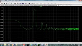
Here is FFT at 1kHz 1W on 8ohm.
ddo
Attachments
power/voltage drops from 200W into 8r0 to 375W into 4r0, i.e. -0.56dBW
and drops from 375W to 701W into 3r0, i.e. -0.59dBW.
These two drops seems surprisingly close.
I would expect the drop into 4r0 to be much less than the drop into 2r0.
How did you measure these output figures?
Were the mains supply voltages the same? Did you meausre the mains supply voltages for all three output power measurements?
2r0 loading is an easy load for a 4ohm rated amplifier.Wouldn't you need more than 4 pr for 2 ohm operation at that power output ...?
I would expect every 4ohm rated amplifier to be able to drive a 2r0 test load without any difficulty. The only problem would be extended testing raising the heatsink temperature above the design target limit.
If you need a 2ohm rated amplifier, then it must be able to drive a 1r0 test load and preferably lower.
- Status
- This old topic is closed. If you want to reopen this topic, contact a moderator using the "Report Post" button.
- Home
- Amplifiers
- Solid State
- TT amp, 200W/8ohm, 701W/2ohm