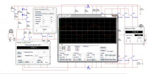
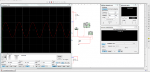
I v made an amplifier based on the schematic of crown pulse worked prety well,then i decided to have a little fun with the schematic in multisim and the result is the schematic below it works prety well both in reality and in multisim.I want some opinions about the schematic I made, is it room for better or its good the way it is.In the schematic i used bf622-623 in the hom build one bf423 422.Iv made a simetric power amp of crown pulse but that i don think i can post it.
I
I
Attachments
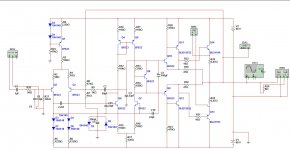
this a fairly common topology I have come across it many times basically the Hitachi application circuit that was originally published with the application notes for the then new MOSFET devices 2SK/2SJ pairs back in the 80's which they also used in their HMA range of PA's.
I have seen it in the Goldmunn "clone" discussed elsewhere on here but this variant was taken from a design for the MST-Rauch DVT PA's from the late 80's with some refinements of Constant current sources added as well as the extra drive pair driving 2SK176/2SJ56 output devices the additions in this are the "rubber diode" or "amplified diode" in the output bias arrangement. I once discussed the behaviour of this topology with Bob Carver when he was still with Carver Professional whilst assesing the product for a client who was considering it for a distribution deal.
a great deal of change the the "subjective audio" can be achieved by altering the "TFM" which he did much research in at some point. I always notice that this class A drve circuit is always operated at a fairly low Iq which does little to make it sound as good as it could or should. my variation on this same topology runs at a much higher Iq with the devices running a lot hotter as true ckass A should IMO the biggest mistake made by all the numerous makers of "MOSFET" PA's was to not have enough current to drive the gates of these output stages in the belief that they did not need or require it completely negating the the stages capacitance that does indeed require it to perform well hence the addition of the extra pair of drivers running directly coupled to the power rails to make sure current was available to the gates this makes for a very "fast" amplifier although particular attention had to be paid to stability issues but it is a good circuit just needs the TFM issues addressed and it will be excellent
- Status
- This old topic is closed. If you want to reopen this topic, contact a moderator using the "Report Post" button.