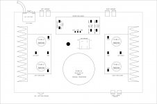
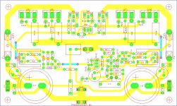
After building my monoblock amplifiers, it's now time to put them in an enclosure.
Ive added a rough lauout, but I'm abit confuced about the ground wiring.
Can someone pls advice on how to connect the grounds in this type of layout.
Time to show those Paint skills .
.
Thanks
Ive added a rough lauout, but I'm abit confuced about the ground wiring.
Can someone pls advice on how to connect the grounds in this type of layout.
Time to show those Paint skills
.Thanks
Attachments
Last edited:
Ive only started on drawing out the protection board circuit,
Not really decided on what it will do, just been thinking of what I would like it to do,
Originally I liked the idea of pulling power from the amp supply, but thats undecided at the moment, might use a secondary transformer, and features would be taken into consideration.
Not really decided on what it will do, just been thinking of what I would like it to do,
Originally I liked the idea of pulling power from the amp supply, but thats undecided at the moment, might use a secondary transformer, and features would be taken into consideration.
Thanks for the link OnAudio, but each amp has its own Filtering,
thats what confuses me.
Or should the idea of each module having its own capacitor filtering be changed to
-local decoupling, with modules fed from singular big capacitor bank.
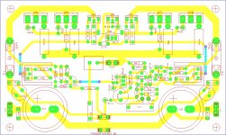
None of the boards to be used in final project have been etched yet, just some prototypes,
If I need to make changes and re-etch boards that ok,
using this as a hoby and learning experience,
so taking it slowly and redoing things untill Im happy with the result
Regards
thats what confuses me.
Or should the idea of each module having its own capacitor filtering be changed to
-local decoupling, with modules fed from singular big capacitor bank.
None of the boards to be used in final project have been etched yet, just some prototypes,
If I need to make changes and re-etch boards that ok,
using this as a hoby and learning experience,
so taking it slowly and redoing things untill Im happy with the result
Regards
Last edited:
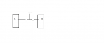
ummm, if Naim, big fat capacitor local to the transformer / rectifier then feeding power to boards with smaller local decoupling. Think of the big fat cap as a (+) and (-) star point if taking this approach.
But for me I like the idea of big local decoupling fed from stars at the rectifier, (+) rectified feed possibly via a small valued power resistor (or choke) to somewhat separate the PSUs of each channel.
A
But for me I like the idea of big local decoupling fed from stars at the rectifier, (+) rectified feed possibly via a small valued power resistor (or choke) to somewhat separate the PSUs of each channel.
A
You seem to be connecting dirty grounds (e.g. transformer secondary CT) to clean grounds (e.g. star point). Everyone does this, but I don't know why because it guarantees buzz.
First make sure you amp PCBs have a dirty ground connection for the smoothing caps and a clean ground connection for signals. These two grounds can be/must be connected on the PCB. Each dirty ground should go to the CT. The existing thick lead from CT to star ground must be removed. The clean grounds from the amp PCBs should go to star ground.
Doing this will keep charging pulses away from the star ground but you will have ground loops. Unavoidable if you have one secondary/bridge feeding two separate cap banks and amps on two separate PCBs. The whole amp architecture, including PCB design, must take account of grounding.
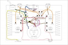
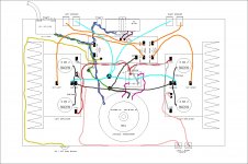
Sill confused,
I am leaning toward removing the 10 000uf s from the boards and having the amps share a capacitor bank.
But if I didn't, would this be correct wiring,
If not please tell me what to change.
Regards
I would advise you read this article:
http://www.diyaudio.com/forums/diyaudio-com-articles/163575-audio-component-grounding-interconnection.html
Hehe Im confused about my boards to,
Here are two im thinking about,
But with advice from the vast knowledge of this Forum members,
Im sure I'll get there in the end.
Learning lots so far.
Ill only etch final boards when I get all this sorted,
I have made proto boards, but Im hoping for no buzz on speaker.
Ive posted there PCB on other thread to, hoping badly to get this resolved
Regards
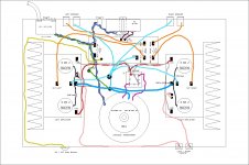
Attachments
Thanks tauro0221, I had some time today to scope my proto board,
There was a feint zzz sound when placing ear close to tweeter,
On scope there was peaks of about 100Hz,
I decided to take main smoothing caps off amp pcb, (was taking star between caps,) re-wiring same as in your diagram but just with mono with T off supply caps to star.
zz sound is gone and only feint sss sound that ive heard on amps before, so Im not to concerned about it.
The scope shows that the 100hz is gone
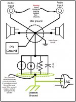
There isn't a separate 'audio ground' attached to the star point. The star point is the audio ground. Note that the PSU ground connection must come from the clean end of the PSU, not the dirty end.tauro0221 said:I have a basic sketch on how to ground the amplifier to avoid hums.
See the attachment. This will give you an idea on how to do the grounding.
The network between audio ground and safety ground simply needs one connection to safety ground and one to star ground. The distance should not matter. If it does matter then you may have some other ground problem.
cause of hum...
usually the cause of hum is a poor contact between chassis and star gnd. this creates small voltages enough to cause hum in your speaker .this small voltages rides with the input signal usually input gnd.the trick they used by implementing a resistor is to force back this small voltages back to this star gnd because the resistance is much higher than the poor contact between pcb and chassis.
star gnd. at pcb is effective if it is closer to the main star gnd.purpose of star gnd at pcb is to isolate each gnd. returns at the point of intersection and should be zero resistance.if your wire at pcb is long going to main star gnd, current will travel to other gnd returns rather than going to main star gnd.
well you could use a copper plate and serves as your star gnd. instead of stacking all your connectors at one screw you can soldered it for a better conduction.this plate also will act as a gnd plane for your gnd returns increasing efficiency of the amplifier.and place it as close to the amplifier pcbs.
make sure that your gnd. input connector(rca) is not touching the chassis.
regards,
joel
- Status
- This old topic is closed. If you want to reopen this topic, contact a moderator using the "Report Post" button.
- Home
- Amplifiers
- Solid State
- Ground Wiring Advice Needed