Hi Everyone,
Was wondering if someone could help me as I'm either missing something obvious or having a stupid moment.
Have just got a Yamaha DSP-AX750se surround amplifier that I'd like to repair, I bought it faulty thinking it would be something obvious.
Plugged in and switching it on, nothing happens, the unit is completely dead.
Took the lid off, and looked for signs of a component blowing. But all looks fine.
Took some measurements AC in is fine, but there is no AC out to the transformer. Believe the fault to be in the Sub Trans area. Investigated after obtaining the service manual and a few of the voltages are missing.
Have the service manual, if someone would be willing to point me in the right direction. Or am I in the wrong area all together.
Never worked on a 8.1 amplifier before so all help would be amazing")
Pictures and service manual on request
Was wondering if someone could help me as I'm either missing something obvious or having a stupid moment.
Have just got a Yamaha DSP-AX750se surround amplifier that I'd like to repair, I bought it faulty thinking it would be something obvious.
Plugged in and switching it on, nothing happens, the unit is completely dead.
Took the lid off, and looked for signs of a component blowing. But all looks fine.
Took some measurements AC in is fine, but there is no AC out to the transformer. Believe the fault to be in the Sub Trans area. Investigated after obtaining the service manual and a few of the voltages are missing.
Have the service manual, if someone would be willing to point me in the right direction. Or am I in the wrong area all together.
Never worked on a 8.1 amplifier before so all help would be amazing
Pictures and service manual on request
Perhaps the former owner had a big house party and ran it way too loud for way too long into multiple speakers and the main transformer has had its thermal fuse blown. You have no idea how many amps I have seen come in on a Monday in this condition. Check for continuity on the primary winding, if it is open the transformer is toast.
Sorry for the late reply been busy with work projects.
Measured the primary for continuity all is ok, no voltage is getting to it though.
Had a look at the circuit diagram and did some meter readings.
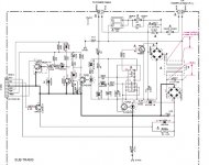
Two test points are labelled on the diagram for the sub trans area T401, I get the 66v input but no 8v output so I'm guessing the stepdown transformer for the stand-by supply has gone down.
Attached a copy of the sub trans area. All help welcome. Even if its just to say im doing something wrong or in the wrong area
Measured the primary for continuity all is ok, no voltage is getting to it though.
Had a look at the circuit diagram and did some meter readings.
Two test points are labelled on the diagram for the sub trans area T401, I get the 66v input but no 8v output so I'm guessing the stepdown transformer for the stand-by supply has gone down.
Attached a copy of the sub trans area. All help welcome. Even if its just to say im doing something wrong or in the wrong area
Attachments
Sorry for the late reply been busy with work projects.
Measured the primary for continuity all is ok, no voltage is getting to it though.
Had a look at the circuit diagram and did some meter readings.
Two test points are labelled on the diagram for the sub trans area T401, I get the 66v input but no 8v output so I'm guessing the stepdown transformer for the stand-by supply has gone down.
Attached a copy of the sub trans area. All help welcome. Even if its just to say im doing something wrong or in the wrong area
That 66v on the primaries ...Where is it coming from? are you sure it is suppose to be 66v and not 110v?
Hi,
I have just found this post after experiencing similar problems with my DSP-AX750SE.
Initially the unit failed to power up, but after unplugging for 10 mins it would power up and work fine. Now it fails to power up at all, but a faint flash can be seen if you observe the blue (pure direct) LED closely.
I have checked for continuity of the primary and secondary windings on the main transformer and both are ok.
I have also checked for 240V supply to the primary windings and here is where i'm confusing myself.
If I disconnect the primary winding plug from the board, I have 240V between the two pins (on the board). When I plug the transformer back into the board, I have 0V between these two pins, I have even checked each pin to Earth and still nothing.
I was hoping someone on here may of had a similar problem and can point me in the right direction.
Many thanks,
Tristo
It looks like the small transformer isn't run straight from the line, but via some sort of pulse width modulation like an SMPS on its primary. Seems total over kill to me where a regular line-powered transformer would have worked!
Hm, having carefully read, it seems you should only have 56V on the primary in Japan, where the voltage is 100V. There should be 158V there in Europe on 220-240V. My guess is that the circuit around IC402 is trying to detect line voltage/frequency and getting it wrong. Too low a primary voltage means too low secondary voltage = nothing works.
Look at page 75 for a diagram of the sub transformer PCB, page 81 top right for the schematic. You'll see a parts matrix below it. Check the parts on that list in the "G" column. My gut says check C405, R412 and C406.
C405 should be a 22n X2-rated capacitor, such as this
Jitter,
Thank you so much for providing the manual and such a speedy reply
I took your advice and metered from the mains plug to the pins on the board (going to the main trans).
The N line was ok
The L line was O/C
Briefly checking the drawings, this has drawn me to relay RY401, and to find why this is not firing. I have not managed to carry out any further checks as yet.
Jaycee,
Your reply came through just as I was about to start a night shift.
Therefore, I have not managed to do any tests yet, but have spent some time looking at the drawings of the Subtrans circuit and trying to follow them through.
Thank you so much for your valued input, suggestions and explanation of what is going on here. I have only briefly managed to look at the board and the components you have mentioned, but cannot see any obvious signs of damage. When I have a little more free time, I will do some more tests and feed back.
Thank you both again for your much needed help.
Tristo
You're welcome. You didn't mention the fuse, but I assume it's OK.
I've been trying to get my head around the PSU of this amp, but it gave me a headache. On the plus side is that the schematic has links (the yellow boxes) so you needn't scroll until you're blue in the face...
The way I see it is that the subtrans powers the microprocessor (uP) via S10 to IC501 to +5M/+5S/+5BU and is checked by the very same uP (PDET might mean Power DETect). At power down PDET becomes low quickly (before the main PSU caps have drained) and the uP will probably switch off the speaker relay te prevent strange noises and thumps.
C402 probably creates a slight delay after power on before the uP gets reset (/RES).
If subtrans power is up, than the uP activates PRY (which I assume means Power RelaY) and that switches on RY401 to connect the main transformer to the mains.
I agree with jaycee that the subtrans is the place to start measuring. It is on page 86 (not 81) top right. If it doesn't work, the rest of the amp can't work either.
Last edited:
My job is electronics too.
I repair Hi-Fi's for a living. I repair lots of Yamaha Amplifiers, Sound Bars etc etc.
C 405's value changes and does not pass as much AC through it to IC 402 as it should preventing the Standby Circuit from operating correctly.
Not a hunch.
James.
I repair Hi-Fi's for a living. I repair lots of Yamaha Amplifiers, Sound Bars etc etc.
C 405's value changes and does not pass as much AC through it to IC 402 as it should preventing the Standby Circuit from operating correctly.
Not a hunch.
James.
See here also
Yamaha YSP-1000 - Power problem | AVForums.com - UK Online
Similar power supply. Same Cap.
No hunches were harmed in the writing of this post.
Yamaha YSP-1000 - Power problem | AVForums.com - UK Online
Similar power supply. Same Cap.
No hunches were harmed in the writing of this post.
Last edited:
That makes things different.
My job is in industrial electronics (manufacturing) and indeed, for certain relatively often occurring faults in a product I'm specialized in, i just know what to replace without taking any measurements.
If C405 is a well known offender in these products, then I'd agree on replacing it anyway. I would also consider this a flawed design and I hope Yamaha doesn't use it anymore.
Last edited:
Many many thanks to everyone who has taken the time to look at the drawings and help diagnose this for me. I have learnt a lot in the last 24 hours.
I am currently not at home so cannot do any checks atm, but I am pretty confident that cap seems to be this issue. I'm lucky enough to live near a maplins, so I will let you know how I get on.
One last quick question. We had a couple of power spikes at work last week. Do you guys think this could be the cause of the damaged cap? Or is it just worn out through normal use? I'm pretty sure the amp is plugged into a surge suppressor extension lead to protect against this.
Thanks again,
Tristo
It's the function of X- and Y-rated caps to prevent damage to equipment and injury to persons (link).
For obvious reasons these should never go short circuit in case of damage. That leaves decreased capacitance as a failure mode. Those spikes may well have caused damage to the caps, esp. if the malfunction occurred shortly after. Replace only with the same type!
I've heard of damage to equipment plugged into surge suppressors before, so I question if their capability of protecting against spikes.
I think "normal wear" would need at least a decade to appear. At work we had a lab power supply belch out smoke as a result of a failed suppression cap on the mains entrance. Within a few weeks, another one of same make and age developed the same fault. These PSUs were well over a decade old and in daily use.
Last edited:
Fixed
A big thank you to everyone who helped with my issue.
On Sunday I replaced C405 with a new one purchased from Maplin (N38CN / 89p)and unit fired up perfectly. The original cap look fine and had no obvious signs of damage, but when tested, was only reading 6.6nF and not the stated 22nF.
The new capacitor is rated for 1250V, a lot higher than the 630V specified.
Do you guys recommend that I change it again for one of the correct rating, like the one linked to by Jaycee in an earlier post?
I will have to get this capacitor mail order, which Is why I went for the Maplin one originally.
Thank you all again for all or your help.
You have certainly saved me a lot of money getting the amp sent away and tested.
I will definitely be recommending this forum to friends and family and be checking back here again.
All the best
Tristo
- Home
- Amplifiers
- Solid State
- Yamaha DSP-AX750se........Dead, No Power