According to #16 of this thread, A240 & A270 are similar amplifiers. It may be worth the chance of help if nothing else is available.
I do have the service manual for the A240 - you will also find a partial schematic here on diyaudio if you do a search. Do you need it to service the amp? Can you post details?
(I am often asked about schematics from british amps from the 80ies and 90ies - I get a little bit hesitant giving it all away without further infos about the individual project...)
(I am often asked about schematics from british amps from the 80ies and 90ies - I get a little bit hesitant giving it all away without further infos about the individual project...)
Hi all. Thanks for the info. Yes, I need the schematics for a repair that's on the bench at the moment. It had a transistor about half way down the strip that was leaky all round. It looks like it's half of a long-tailed pair. I replaced it with an identical one, but that channel produces no audio. It has equal levels of signal to the working channel up to somewhere near the stage that had the bad transistor in, then it all disappears. There is no sign of any other component being faulty, and cold resistance checks between channels are pretty much identical. There are some slight discrepencies in voltages, but nothing really significant. I'm a bit suspicious about the relative pinouts of the original and replacement transistors. Although both are BC546's, I'm sure that I have in the past come across plastic TO92 BC series transistors where the emitter and collector leads are reversed. I could verify this if I had schematics. I'm loathe to try just reversing the replacement trnasistor, as I'm sure any of you that repair DC coupled amps are aware of the potential consequences of getting it wrong - if it's not already ... If you see what I mean ... 
So if anyone has amanual. or anything close for another model in the series, I would greatly appreciate getting a squint.
TIA
Arfa
So if anyone has amanual. or anything close for another model in the series, I would greatly appreciate getting a squint.
TIA
Arfa
So if anyone has amanual. or anything close for another model in the series, I would greatly appreciate getting a squint.
TIA
Arfa
All that I have been able to find is owner manuals - and this old thread that has some information....
http://www.diyaudio.com/forums/solid-state/125742-qed-a240cd-blows-fuse-powerup-4.html
I have scanned the pages what I found for a more or less complete service manual for the QED A240 Ser.2. It is scanned from copies from faxes, so do not expect a very good quality. But it should be enough for repairing purposes.
The PDF is too big to upload here, so please PM me for the complete one.
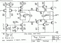
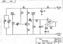
Additional here two images of the powerstage and the line buffer of the A240 (without components values):
The PDF is too big to upload here, so please PM me for the complete one.
Additional here two images of the powerstage and the line buffer of the A240 (without components values):
Attachments
Ok. In case it helps anyone in the future, the schematics for the A240 do seem to match the A270 in terms of both circuitry and component identifiers. My thanks to lohk for being kind enough to scan them and send them to me.
The problem turned out to be R33, 18k. It is one of a pair of 18ks, the other being R32 which feed a bias supply to the transistor in the bottom end of the longtailed pair Ta & b or Tc & d depending on which channel. This transistor is T4 in one channel, and T12 in the other. This bias supply comes from the small relay that is time delayed after switch on. I guess that it's an anti thump muting circuit.
The resistor was completely open, but showed no sign of distress at all, In fact it is quite a 'chunky' device compared to all the others in there, and I would guess it to be at least 0.6 W. Most probably a voltage stress thing, as it has around 76 volts across it when working. This is because it is fed via the relay from the +38 v rail, and the pair of diodes that it feeds to develop the 1.3v bias for T4 (12) are returned to the -38v rail, along with T4's emitter resistor.
So, a nice fault in the end, and I'm sure the owner will be delighted to get it back. Thanks all for the comments and help.
Arfa
So, a nice fault in the end, and I'm sure the owner will be delighted to get it back. Thanks all for the comments and help.
Arfa
That is some mighty fine troubleshooting there Arfa - Well done!!!
Hi Arfa ..
I have a problem with an A270 that one output to speaker is failing/falling .... no music or occasionally .. could it be that a Elco is dead ? .
If you have any suggestions would be nice.... I have no scope ?
I did study electronics ages ago ..but went into aviation instead .
I have a problem with an A270 that one output to speaker is failing/falling .... no music or occasionally .. could it be that a Elco is dead ? .
If you have any suggestions would be nice.... I have no scope ?
I did study electronics ages ago ..but went into aviation instead .
- Status
- This old topic is closed. If you want to reopen this topic, contact a moderator using the "Report Post" button.
- Home
- Amplifiers
- Solid State
- QED Vintage Amp ...

