Fitting Big capacitors in a QUAD 405
Capacitors involved directly in the signal path always degradates the sound. That's why we want to use the better ones available. In particular Wima MKP10's
metalized polypropylene are widely used and well suited for such applications when looking for cost/performance/small size balance. Wima MKP10 have also a
big cons: short leads (only suitable for direct pcb mount). Other more sophisticated (and bigger) caps can be used but not only will unfit the pcb but also
will unfit the entire amplifier enclosure (and will add very long wires and poor mechanical self-supporting characteristics).
As part of my Quad 405 general upgrade (including new OPA and gain (noise) reduction, among others recommended by Bernd Ludwig and Keith Snook), I wanted to
replace/upgrade the old capacitors with better ones, but always have to answer the same question: will the new caps fit on pcb? and the answer almost all the
time is NO.
For this reason most Quad 405 capacitor upgrades and mods almost everytime uses MKS (polyester) or similar caps that will fit pcb without trouble, but this is not my goal in a real and noticeable cap upgrade from the original.
I wanted to get the better performance replacement caps as possible:
First I replaced All the electrolytics (for aging reasons) and here there is no problem at all, as they are not involved in the signal path and fit as the
originals.
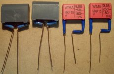
Replace the input coupling capacitor C1 (direct on signal path: deserves the best) .68uF with Wima MKP10 250Vdc 180Vac 10%.
Replace the OPA local feedback C4 cap (direct on OPA feedback signal path) .15uF (new value for OPA gain reduction replacing also R6 with 100K). Replaced
with Wima .15u MKP10 630Vdc 400Vac 20% (has same size as the C1 replacement).
Replace the low pass filter C6 cap at the OPA gain stage output (not direct "on" signal path but with influence in the overall signal filtering) with Wima
MKP10 1nF (pair measured and selected after best capacitance match). This Wima has not problems as will fit on pcb without any further modifications.
C2 is a big deal and compromise. Almost everyone uses electrolitycs due the big capacitance (between 33u - 100u) and compensates fitting little polystyrenes
or polypropylene film in paralell or "bypass" . For C2 I was looking for 33uF film capacitors with low voltage characteristics (looking for the the smallest
size and higher capacitance replacement). I finally found French made film capacitors at Digikey, they are Metalized Polyester film rated 75V with almost the
same size than Wimas MKP10. With this selection for C2 there's absolute no electrolitycs with influence in the signal path.
For C6 I followed Keith Snook suggestions and placed 120pF polystyrene rated 630V. For the "uncomfortable" C11 (some think have influence on 405 sound,
others no) I preferred to stay on the safe side replacing with polystyrene film 1000pF 160V 2,5%.
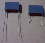
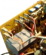
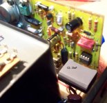
At this time we have Three big capacitors (C1, C4 and C2) with short pins to place on the QUAD pcb. C6 fits perfect as well as the small polystyrenes. In
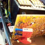
order to make larger leads I used: terminals, .6-.7mm copper wire and shrinkable insulation. The objective is to extend the capacitor leads or pins adding aprox 2 cm (or less) in the safest way possible.
All we know that with longer leads or pins then more "noise" will be added to the signal, and thats why we should use the shortest as possible; but when putting on balance the benefits of good capacitors (less sound degradation) vs. longer leads, the risk of introducing noise (if any) is in my criteria totally acceptable and not noticeable.
I'm not a good photografer but think my pictures show the way I used the terminals, the .6-.7mm copper wire and the shrinkable wire insulation.
Terminals used: non insulated terminals for wire splices 22-26 AWG or 20-24 AWG Digikey part number 8-324001-1-ND or A09010-ND (after carefully crimping with any crimp tool I putted some soldering on terminal middle opening in order to make the best galvanic conection possible).
Capacitors used: wimas are well known capacitors and easily found in Mouser Catalog or other similar supplier catalogs. Capacitor used for C2 is: AVX Corporation FFB series (FFB14D0336K) 33uF 75Vdc 45Vac Polyester metallized film 10%. Digikey part number 478-2589-ND
I know C2 metallized polyester can be also "bypassed" with some blessed cap, but I didn't do that.
Results:
The first listening sessions are deceptive because the "burn in" process: bowed strings like violins or cellos sound more metallic and restricted (similar as the sound difference beetwen guitar played with steel or nylon strings), but after some hours of listening the sound becomes totally different, more sweet, transparent and very clear.


Last edited:
Most amplifiers seem harsh each time you switch on and listen. After a few hours, fatigue makes all audio sound smoother, better, more clear in details, huge sound stage etc. with nothing changed even. Subjective assessment is essential but it varies a lot with your condition and expectancy.
It takes experience to be a good judge of how the amplifier will sound when you become accustomed to any changes. I only wish I was that good!
'Nice ideas but the leads must be shorter than the last pics shows. Good 405s do sound great, though.
It takes experience to be a good judge of how the amplifier will sound when you become accustomed to any changes. I only wish I was that good!
'Nice ideas but the leads must be shorter than the last pics shows. Good 405s do sound great, though.
Last edited:
- Status
- This old topic is closed. If you want to reopen this topic, contact a moderator using the "Report Post" button.