here is part of a schematic i have seen where is a few words the author claims that tuning of the trimmer ( marked in blue ) by inputting a 20kHz sine wave and measuring the harmonic distortion on the output. When turning the pot you should see an increase or decrease in harmonic distortion, simply turn the pot until you find the minimum value obtainable.
would you like to comment the above practice ?
Kind regards
sakis
would you like to comment the above practice ?
Kind regards
sakis
Attachments
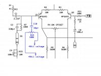
R34 / C10 will inject high frequency signals from the supply rails into the input. I cannot say I am familiar with this but would suggest that the consequences will be heavily dependent upon
- Your specific rail decoupling
- The load you are driving, i.e. how much of the signal appears at the points driving R34
- layout and grounding
On this basis I would consider it somewhat hit and miss.
I would be interested in other interpretations as to it's use.
As an aside, R4 looks like it is there for balancing the differential pair - I wonder if the circuit would be better off with a current mirror as a load for the differential pair...
D
Deleted member 148505
I'm not a fan of tube sound but do like the AKSA where I can dial in how much harmonics I like. The amount I use is much less than the genuine AKSA and heads towards the lower levels in the LF55. I'll be doing this with the B-AKSA as well.
Is this what rabbitz referred to?
D
Deleted member 148505
You can click the > button after the quoted's name
Anyway, here's the link.
http://www.diyaudio.com/forums/solid-state/168554-based-hugh-deans-aksa-55-a-29.html#post2255020
Anyway, here's the link.
http://www.diyaudio.com/forums/solid-state/168554-based-hugh-deans-aksa-55-a-29.html#post2255020
Last edited by a moderator:
I would be somewhat concerned about increased susceptibility to RF injection, since it's likely the same balance won't occur for all frequencies.
'Agree with googlyone that without a full understanding of the grounding and supply decoupling, the effectiveness would be uncertain.
'Agree with googlyone that without a full understanding of the grounding and supply decoupling, the effectiveness would be uncertain.
This I have never seen before. After replace the capacitor against a resistor (1-5 meg ohms) this looks more like a topology for an offset adjust.here is part of a schematic i have seen where is a few words the author claims that tuning of the trimmer ( marked in blue ) by inputting a 20kHz sine wave and measuring the harmonic distortion on the output. When turning the pot you should see an increase or decrease in harmonic distortion, simply turn the pot until you find the minimum value obtainable.
would you like to comment the above practice ?
Kind regards
sakis
D
Deleted member 148505
Well no secrets for me the part of the schematic is from a Perreaux amplifier and as about the above comments truly the Perreaux is state of the art when it comes to decoupling and bypass of rails together with topology and distribution of power
there is a combo of 3.3 mfd +0.1 top of the filter capacitors
there is a local 100 mfd+3.3 mfd +0.1 mfd for the rails
and a copy of the above for the drive circuit after of course a resistor and diode ...
I don't know if this improving the picture or not and as said this circuit will work better depending on the above given details
Yeap i am will to try the above combo that will be rail +LTP decoupling and with the given circuit added to see how its going to work in the P3a
obviously inserts the ""modulation" of rails
BUT only if the rail modulation is in phase. If the rail modulation is 180 out of phase then the effect cancels out.
dc
- Status
- This old topic is closed. If you want to reopen this topic, contact a moderator using the "Report Post" button.
- Home
- Amplifiers
- Solid State
- reducing thd