I'm looking for a nice PDF scan of the Australian Edition of December 1972 Electronics Today artical for the ETI-413 100 watt guitar amplifier.
It was latter reprinted in Top Projects, Vol-2 ( I think ??? ).
Way back in 1978, when I was a young 3rd year Radio/Tv Apprentice at RMIT in Victoria, I very much modified the ETI-413 amp for 600 watts RMS output into 4 ohms. I now want to rebuild the same design in a more modern format.
[ A bit of history - The original bridged amp I ended up with had 48 output transistors ( 24 devices per channel @ 50 cents each in those days ) 2N3055/ MJ2955 running on two custom made 90volt @ 15 amp power supplies. It was a true blue 1,200 watts RMS before clipping - just to use in my bedroom for playing Black Sabbath, Deep Purple & Led Zeppelin music. Ah those were the days !
Oh yes - I had my speakers catch on fire in the bedroom - being 2 floor to ceiling speaker stacks - when I cranked the wick up too much and burn't out all 8 dome tweeters. Smoke was streaming out of the boxes like nobody's business.
On another occasion the local Police arrived at 4 pm in the afternoon to ask me to turn down the volume, as the neigbours complained quite bitterly about the noise.
10pm was the cuttoff point for loud noise in those days, but mine was at 4 pm in the afternoon.
I latter fitted a similar large amp into my Holden HQ Panel Van ( but only only measly 200 watts RMS ) and was told "I was crazy" back then.
I just responded and said "I was ahead of my time" - as today, they have "thousands" of watts in their cars. ]
To do this project - I need the old article to recall my memory ( which is fading fast with age) of the schematic details.
Any assistance would be greatly appreciated.
Regards - Kimbal
My contact email is - kimbalsummers@hotmail.com
Had to smile when reading your comments.. that amp must of looked a real monster, what type of case did you make for it?..
Old amp circuits seem to sound better that some newer circuits or is that just me?..
Anyway i'll do some checking and see what i can come up with regarding this circuit plans.
regards.
Old amp circuits seem to sound better that some newer circuits or is that just me?..
Anyway i'll do some checking and see what i can come up with regarding this circuit plans.
regards.
The UK version of ETI magazine was not the same beast as the Australian edition that the OP refers to. It would have been a memorable project if it had been shared by the UK publication, as in fact the original 100W amplifier was contained completely in the largest (then available) size Hammond diecast box! 
The project was available as a kit in various stages of completeness, had 2 pairs of output transistors on a generous sized PCB and was tough, as suited the use. It was actually better sounding than the average guitar amplifier of the day and later utility amplifier designs, which tended to be too cheaply specified. I recall using a few as PA amps for small venues, stage amps etc.
Obviously, to squeeze more power out, a proper heatsink and case was necessary and I had a lot of construction difficulty scaling up to 250W on a budget, as required by our band at the time.
Ok here's the whole story from scratch.
This is stretching my memory some nearly 35 years ago. Mind you I was just on 17-18 when I did this project. Many 17 year olds can't even use a screw driver today, let alone "design" and build a functioning 1,200 watt amplifier / sound system for their bedroom.
I built my first ETI-413 ( Version-1 ) from second hand black & white T.V parts. I purchased a few things like, the TT801 / 802 transistors and some electrolytics, etc. The rest was scrounged from my junk box spares found in hard rubbish collections and old radios passed onto me.
The original "PCB" was made from a chocolate brown paxolin board, obtained from our Form-4 Electrical Class at Technical School ( paxolin is somewhat like kitchen laminex - paper resin based insulation material used in very early PCB's ).
Yes we did REAL electrical classes in 1973/4. Form-4 students built a battery charger, while the Form-3 students built a crystal radio ( using an OA91 diode ) and one transistor set ( using an AC128 ) with a 3 volt battery.
The Form-4 students had to make there own metal box in sheet metal for the charger, and actually wound their own power transformer as part of the project including the cutting out and fabricating the wire bobbin from hi voltage fibre board.
They had to stack the E & I laminations in as well and varnish the final transformer. completed it had a 2 inch stack and was around 15 amps at 6 and 12 volts.
Today that would not be allowed - not in Queensland Australia - as the dear little vegemites, just might electrocute themselves and Occupational Health & Safety ( O.H.& S ) would start a law suit on the school. ) It's no wonder kids are wrapped in cotton wool and no longer able to read, write, or spell any more.
I was little more advanced -( being self taught in electronics at 13, seen as a crazy science nutter into radio and tv back then - today we call guys like me "geeks" ), plus becoming quite serious about audio amp design. I started out with tubes but eventually went solid state, because I could not find decent output transformers. Oh - I had a bunch of S.E Rola 5k-3.5 ohm transformers trying to make Hi-fi come out of them with complementary POWER transformers used for the bass response - but something was not quite right, as I latter learn't.
I had no money, nor the means to wind such at home - so I looked for alternatives to the hifi problem. the alternative was to scrap my tubes - sob, sob, and build big amps with transistors. That was the dream !
My first sound system was all tube radiogram amplifiers using speakers boxes made from Black and white plywood timber TV cabinets with 8 and 12 inch speakers inside. In all I had scored some 24 Tv sets from a deceased Tv repairman's estate, and from that built two floor to ceiling speaker stacks in my bedroom. The deceased estate came with a pile of RTV & Hobby mags as well and a few data books, suitcase of tubes and two multimeters. A total of 50 watts aprox made up the sound system with smaller 5-10 watt amps ( 6V6GT and 6AQ5 output tubes single ended and all running on a stereo crystal cartridge record player - the old " brick on a nail " type turntable ).
Back to the ETI-413 version-1 amp. The PCB was drilled out with 1/32 inch holes drilled in the same layout as the original board; using 2 pair phone cable solid copper wire for connecting links between components underneath. It was crude, but neat and it worked.
The old AY 8149 / 9149 T03 devices made by Fairchild used in the original design were getting scarce even then, and being replaced with the 2N3055 and MJ2955. So went for those.
All heatsinks were bent aluminium sheet made at school in my sheetmetal classes, as were the power transformer and even the wire bobbin. The battery charger class project was dropped for me, and I built my amp instead. The Power transformer was rewound to give the correct voltages - with some help from my electrical teacher. The wire used was a little thin and so the output current was about 1 amp instead of 1.5 amps. I had to use what was on hand. I could have got around it, with bifilar winding the secondary as the room was available on the bobbin to do this, but I was not that advanced inb transformer construction.
The final amp was eventually made in an old 807 valve amplifier that was gutted and recycled for the round style 1940's case. The whole amp worked first time I switched it on, as it took me months to build and a lot of rechecking. Most of it was made on my bedroom floor at home as I had no workshop. All the parts were purchased at J.H Magraths in little Lonsdale street Melbourne. It produced just on 65 watts RMS into 4 ohms and aprox 50 watts into 8 ohms. I settled for the 8 ohm outout to keep the power transformer cool and fitted it with a LM741 mixer preamp and a wooden Tv cabinate for its speaker box. I sold it to my guitar mate after a couple of years for $100 dollars. That was version 1.
Version 2 was the real beast.
I wanted real power - and as much as a kid could get.
I wanted to hear "Smoke On The Water" blasting away as loud as Deep Purple played in real concert. Since they were the world's loudest rockband in 1971/2 and at that time a measured to be +17 db louder than a jumbo jet plane at full roar - I wanted to create the same sound pressure level atmosphere in my bedroom. I believed in feeling my music not listening to it. feeling music rock through your bones is very different to hearing its tranquil sonics. The health dangers of such high pressure sound are now well documented.
To do this the ETI 413 had to run into 2 ohms minimum. So I got out my new TI-58C Texas Instruments reverse polish notation calculator and cruched a few figures. Yeah I needed a few extra O/P devices - like 48 in all @ 50 cents each was going to cost me big bux - a whopping $25 dollars if i used 2N3055. Jumping up to the old 2N3773 150 watt T03 device would be better, but it did not have a PNP compliment at that time - that I could find. So back to the 2N3055 & MJ2955. Anything else available had cost or technical issues with getting the devices implemented.
( Mind you I was on about $47 dollars a week as a 1st year apprentice in 1976. That was a dollar and hour I worked in my trade. Talk about extortion ! )
I read articles on big amps in those days, some using exotic Line output transistors and fancy protection circuits - which became costly and did not sound all that great to the ear. ( some that come to mind were the Phase Linear 700 watt RMS amp, the Crown and Amcron series of big amps which were massive in the late 70's for home use. ) I wanted something just as exotic - but done with a shoe-string budget.
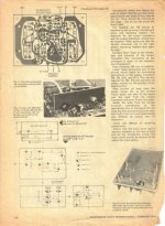
So I built four ETI-413 amp boards from new parts that I purchased - as I was working as a 3rd year apprentice at this stage. The PCB's boards were supplied by a local RMIT teacher who had gold plated them.
There was an article on bridging the ETI 413 and I used that as the basis to work from. It stated a bridged amp could deliver 4 times the power of a single amp. That was 400 watts into 4 ohms. Double that to get back to 4 ohms meant I needed twelve T03 devices per amp.
With four amplifiers that was 48 transistors. These were mounted on four 10 gauge L shaped ally angle 18 inches long; each being bolted with 3/8inch dia bolts & Nuts to a huge 10 gauge alluminium plate. The outside of the plate was fitted with six home made U channel ally lengths around 10 inches long. bolted onto the outside.
The driver stage was using TIP 41/42C devices instead of the BD 139/140 specified in the original ETI article. They were bolted to the same ally heatsink brackets rather than theri own heatsink. Resistors were increased in wattage as well as a few adjustments to their values here and there. Transistors were kept the same through out in the front end and predriver stages, with the exception of glueing the two front end differential pair transistors together and adding in a small pot into their emitters to null out residual DC appearing across the speaker terminals. I think that was 100 ohm pot.
Fuses only were the total protection for the amp. Despite what poepl say I never lost and output transistor under all fault situations. the fuse ALWAYS blew first. they were not fast blow fuses either the cheapest fused you could get 10 cents I think they were at the time. The quiescent current was I recall 15 ma per output transistor, set by the IQ pot in the bias circuit. A total Iq of around 90 ma per rail, per amplifer.
I cranked the power supply from +40 to +45 volts rails. I mounted a 35 amp bridge rectifier in each supply and four massive sprague electros for the two power supplies. 37,000 UF @ 75 volts each they were. I got these from electronic disposals for 10 dollars each. As they were so huge I needed a big cabinet as well as an internal fan to cool it all.
The cabinet was made of chipboard 2 layers of 3/4 inch glued together with 4 inch wood screws used. It was covered with black vinyl and metal corners fitted in the cabinet. It took two men to lift the amp as it was so heavy. The fan was an old 10 inch diameter house fan from the 1960's which I stripped down and used to cool the amp internally. It was tripped with a thermo-transistor relay when the temperature rose about 45 deg C.
I fitted heat vents to the cabinet to aid in cooling the insides. If it got really hot I put a house fan - a Mistrel-Gyro Air Fan - on the rear heat sink to aid in cooling it as it was far from adequate for full output. Ok at low level and small auditoriums and that was it. Big heat sinks were costly if you could get them in those days.
The amp had a level control for each input and a clipping led light ( ETI-??? project ) for each channel as well as leds for the fuse rails and power supply. In the end it looked like a christmas tree on the front aluminium panel. It was all black except the front panel, which I anodised myself at home in a caustic soda bath.
I used two 15 amp fuses in the two power supply rails for each channel. If you put a screw driver across the speaker terminals at full output as i did a couple of times, just to prove its ruggedness, the fuses blew the respective light came on and nothing more happened. Replace the fuses - while full audio was driving only half the amplifier and its still switched on - you might see a spark come off the fuse holder, but in the meantime and you get back on line. No switching diodes were needed for transients spikes either. I don't believe in all that over engineered gobbly-gook for audio amps. Build it for the army as i say and push the crap out of it and if it survives it should hold up under the tightest of conditions. If it does you have good amplifier.
I cannot over emphasize when you build big amps always use more output devices than needed. if you need 3 use 6 if you need 10 use 20. and so on. The fuse should be the only protection circuit and the weakest link, other than the power transformer itself.
As for the power transformer - I used two specially wound 750 VA E&I core transformers ( wound by a friend who worked for ATCO Transformers in Victoria ) 90 volts CT @ 15 amps continuous. They cost me $50 dollars each at that time.
The mains primary had no tapps but an E/S sheild was used between the windings. the transformers could sit at 15 amps all day without getting hot - just warm to the hand at best. Throw that across a 35 amp bridge with a pair of 37,000 uf caps and you had a very mean power supply - even by today's standards. I used two supplies like this - one for each channel without regulation. In fact regulated supplies are the worst thing you can have in a big amp. Regulation is fine for smaller front end stages but the out put has to breath and regulation stifles that ability. As a result transient bass response falls off. The down side to unregulated supplies is the Vce of the output devices has to cope with the wide swing in output potential. Regulation of the power supply has a tendency to push an output device into its SOA way to easily - ( as the supply rail cannot sage it's too stiff ); which limits the ability for the Output stage to remain efficient. I'm sure some of you will disagree on this philosophy but at the end of the day simpler circuits in my opinion are the better.
Same with protection circuits. A well designed amp does not need protection circuits as they play havoc with the audio path. A well designed amp is indestructable to start with; having at best a simple fuse to do the trick - like a 15 amp el-cheapo car fuse. I know it works well - been there done that !
Finally I built in the mid 1980's a version-3 of the same amp it looked much nicer a bit smaller ( now a one man lift of the whole amp ) and had the same power supply - as I gutted version 2 for parts. I used the MJ15003/15004 instead but only needed 24 not 48 devices. It worked equally as well.
Sound-wise these amplifiers were more than acceptable for home and hifi use despite the distortion being around 0.5% or so. The only negative with the ETI 413 was the thump it made at switch off. A de-thump relay would hide that problem, but it was never an issue, more just a symptom of its design.
And just so you know this amp really existed, and I'm not making it all up - I might refer you to Barry Wilkinson's article in Electronic Today International ( Australian Edition ) for February 1980, for "The Brute" ETI-466 300 watt amplifier.
At that time, in late 1979, I submitted my Version-2 ETI-413 Amplifier to ETI office in the hope of getting it published. They thanked me for it, but simply put it in the "too-hard basket".
The ETI-466 article refers to my Version-2 amplifier but says nothing more about it. It was a complex amp for the home constructor - drilling out 48 T03 devices on 4 heatsink brackets - but the ETI-466 in my opinion was not all it was cracked up to be either. In fact I never built the 466 as I had an even bigger amp already.
The ETI FEB 1980 article goes on to say >
" HI-Fl AMPLIFIERS are becoming more and more powerful, and with good reason. Modem recordings, especially direct-cut discs, have a useful dynamic range approaching 40 dB between the quieter musical passages and the peaks of the crescendos. If the quieter passages are played at a power output of 100 mW, which is not untypical in a domestic environment, to faithfully reproduce the full recorded dynamic range of a good record without clipping the peaks would require an amplifier capable of delivering 1000 watts! This, coupled with the current trend amongst some manufacturers to build speakers having quite low efficiency, plus the number of people who like their music loud (and undistorted) makes the case for high power amplifiers very strong indeed.
Over the past six or seven years we’ve had many requests for a high power amplifier, but for the reasons stated previously, we have decided against it. It would have been possible to design a unit using a large number of readily available power transistors in the output - in fact, one design we have seen used a total of 24 devices in the output stage! Difficulties for the home constructor in this approach are obvious, regardless of expense.
For various reasons, a bridge amplifier was ruled out when the design of this amplifier was considered. Hence, a plentiful source of suitable
output transistors was first sought.
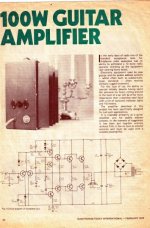
There are really not too many transistors available that meet the requirements. Firstly, adequate safe operating area (SOAR) is of prime importance. Next, and probably of equal importance, is availability. Let’s have a look at the SOAR problem first. Some high power transistors don’t compare too well with the ubiquitous 2N3055 (and its complement, the MJ2955) when operated as an amplifier. Take a look at the set of curves plotted on the accompanying diagram. ( see fig -2 ) This compares the safe operating area curves of a number of power transistors. Operation of any power device must be confined to the area inside the device’s curve at worst case. If the current/voltage operating point is allowed to fall outside the area of the SOAR curve during any part of the operating cycle for the device, it will be
destroyed - with amazing rapidity. Now, the 2N3773 and MJ802 transistors have been around for some time and at first glance would seem good choices for a high power amp, but note that their SOAR characteristics are not much better than the 2N3055. In fact, at 40 V (Vcc) the MJ802 is actually worse. In contrast, the MJ15003 is quite a long way outside the curve for the 2N3055 and therefore has a much higher power rating when used in an amplifier. Hence, the MJ15003 and its complement - the MJ15004, were chosen as the output devices for this design.
Secondly, these transistors are widely used in industrial applications and are available from a number of sources, thus they meet the availability requirement."
Had to smile when reading your comments.. that amp must of looked a real monster, what type of case did you make for it?..
Old amp circuits seem to sound better that some newer circuits or is that just me?..
Anyway i'll do some checking and see what i can come up with regarding this circuit plans.
regards.
This is stretching my memory some nearly 35 years ago. Mind you I was just on 17-18 when I did this project. Many 17 year olds can't even use a screw driver today, let alone "design" and build a functioning 1,200 watt amplifier / sound system for their bedroom.
I built my first ETI-413 ( Version-1 ) from second hand black & white T.V parts. I purchased a few things like, the TT801 / 802 transistors and some electrolytics, etc. The rest was scrounged from my junk box spares found in hard rubbish collections and old radios passed onto me.
The original "PCB" was made from a chocolate brown paxolin board, obtained from our Form-4 Electrical Class at Technical School ( paxolin is somewhat like kitchen laminex - paper resin based insulation material used in very early PCB's ).
Yes we did REAL electrical classes in 1973/4. Form-4 students built a battery charger, while the Form-3 students built a crystal radio ( using an OA91 diode ) and one transistor set ( using an AC128 ) with a 3 volt battery.
The Form-4 students had to make there own metal box in sheet metal for the charger, and actually wound their own power transformer as part of the project including the cutting out and fabricating the wire bobbin from hi voltage fibre board.
They had to stack the E & I laminations in as well and varnish the final transformer. completed it had a 2 inch stack and was around 15 amps at 6 and 12 volts.
Today that would not be allowed - not in Queensland Australia - as the dear little vegemites, just might electrocute themselves and Occupational Health & Safety ( O.H.& S ) would start a law suit on the school. ) It's no wonder kids are wrapped in cotton wool and no longer able to read, write, or spell any more.
I was little more advanced -( being self taught in electronics at 13, seen as a crazy science nutter into radio and tv back then - today we call guys like me "geeks" ), plus becoming quite serious about audio amp design. I started out with tubes but eventually went solid state, because I could not find decent output transformers. Oh - I had a bunch of S.E Rola 5k-3.5 ohm transformers trying to make Hi-fi come out of them with complementary POWER transformers used for the bass response - but something was not quite right, as I latter learn't.
I had no money, nor the means to wind such at home - so I looked for alternatives to the hifi problem. the alternative was to scrap my tubes - sob, sob, and build big amps with transistors. That was the dream !
My first sound system was all tube radiogram amplifiers using speakers boxes made from Black and white plywood timber TV cabinets with 8 and 12 inch speakers inside. In all I had scored some 24 Tv sets from a deceased Tv repairman's estate, and from that built two floor to ceiling speaker stacks in my bedroom. The deceased estate came with a pile of RTV & Hobby mags as well and a few data books, suitcase of tubes and two multimeters. A total of 50 watts aprox made up the sound system with smaller 5-10 watt amps ( 6V6GT and 6AQ5 output tubes single ended and all running on a stereo crystal cartridge record player - the old " brick on a nail " type turntable ).
Back to the ETI-413 version-1 amp. The PCB was drilled out with 1/32 inch holes drilled in the same layout as the original board; using 2 pair phone cable solid copper wire for connecting links between components underneath. It was crude, but neat and it worked.
The old AY 8149 / 9149 T03 devices made by Fairchild used in the original design were getting scarce even then, and being replaced with the 2N3055 and MJ2955. So went for those.
All heatsinks were bent aluminium sheet made at school in my sheetmetal classes, as were the power transformer and even the wire bobbin. The battery charger class project was dropped for me, and I built my amp instead. The Power transformer was rewound to give the correct voltages - with some help from my electrical teacher. The wire used was a little thin and so the output current was about 1 amp instead of 1.5 amps. I had to use what was on hand. I could have got around it, with bifilar winding the secondary as the room was available on the bobbin to do this, but I was not that advanced inb transformer construction.
The final amp was eventually made in an old 807 valve amplifier that was gutted and recycled for the round style 1940's case. The whole amp worked first time I switched it on, as it took me months to build and a lot of rechecking. Most of it was made on my bedroom floor at home as I had no workshop. All the parts were purchased at J.H Magraths in little Lonsdale street Melbourne. It produced just on 65 watts RMS into 4 ohms and aprox 50 watts into 8 ohms. I settled for the 8 ohm outout to keep the power transformer cool and fitted it with a LM741 mixer preamp and a wooden Tv cabinate for its speaker box. I sold it to my guitar mate after a couple of years for $100 dollars. That was version 1.
Version 2 was the real beast.
I wanted real power - and as much as a kid could get.
I wanted to hear "Smoke On The Water" blasting away as loud as Deep Purple played in real concert. Since they were the world's loudest rockband in 1971/2 and at that time a measured to be +17 db louder than a jumbo jet plane at full roar - I wanted to create the same sound pressure level atmosphere in my bedroom. I believed in feeling my music not listening to it. feeling music rock through your bones is very different to hearing its tranquil sonics. The health dangers of such high pressure sound are now well documented.
To do this the ETI 413 had to run into 2 ohms minimum. So I got out my new TI-58C Texas Instruments reverse polish notation calculator and cruched a few figures. Yeah I needed a few extra O/P devices - like 48 in all @ 50 cents each was going to cost me big bux - a whopping $25 dollars if i used 2N3055. Jumping up to the old 2N3773 150 watt T03 device would be better, but it did not have a PNP compliment at that time - that I could find. So back to the 2N3055 & MJ2955. Anything else available had cost or technical issues with getting the devices implemented.
( Mind you I was on about $47 dollars a week as a 1st year apprentice in 1976. That was a dollar and hour I worked in my trade. Talk about extortion ! )
I read articles on big amps in those days, some using exotic Line output transistors and fancy protection circuits - which became costly and did not sound all that great to the ear. ( some that come to mind were the Phase Linear 700 watt RMS amp, the Crown and Amcron series of big amps which were massive in the late 70's for home use. ) I wanted something just as exotic - but done with a shoe-string budget.
So I built four ETI-413 amp boards from new parts that I purchased - as I was working as a 3rd year apprentice at this stage. The PCB's boards were supplied by a local RMIT teacher who had gold plated them.
There was an article on bridging the ETI 413 and I used that as the basis to work from. It stated a bridged amp could deliver 4 times the power of a single amp. That was 400 watts into 4 ohms. Double that to get back to 4 ohms meant I needed twelve T03 devices per amp.
With four amplifiers that was 48 transistors. These were mounted on four 10 gauge L shaped ally angle 18 inches long; each being bolted with 3/8inch dia bolts & Nuts to a huge 10 gauge alluminium plate. The outside of the plate was fitted with six home made U channel ally lengths around 10 inches long. bolted onto the outside.
The driver stage was using TIP 41/42C devices instead of the BD 139/140 specified in the original ETI article. They were bolted to the same ally heatsink brackets rather than theri own heatsink. Resistors were increased in wattage as well as a few adjustments to their values here and there. Transistors were kept the same through out in the front end and predriver stages, with the exception of glueing the two front end differential pair transistors together and adding in a small pot into their emitters to null out residual DC appearing across the speaker terminals. I think that was 100 ohm pot.
Fuses only were the total protection for the amp. Despite what poepl say I never lost and output transistor under all fault situations. the fuse ALWAYS blew first. they were not fast blow fuses either the cheapest fused you could get 10 cents I think they were at the time. The quiescent current was I recall 15 ma per output transistor, set by the IQ pot in the bias circuit. A total Iq of around 90 ma per rail, per amplifer.
I cranked the power supply from +40 to +45 volts rails. I mounted a 35 amp bridge rectifier in each supply and four massive sprague electros for the two power supplies. 37,000 UF @ 75 volts each they were. I got these from electronic disposals for 10 dollars each. As they were so huge I needed a big cabinet as well as an internal fan to cool it all.
The cabinet was made of chipboard 2 layers of 3/4 inch glued together with 4 inch wood screws used. It was covered with black vinyl and metal corners fitted in the cabinet. It took two men to lift the amp as it was so heavy. The fan was an old 10 inch diameter house fan from the 1960's which I stripped down and used to cool the amp internally. It was tripped with a thermo-transistor relay when the temperature rose about 45 deg C.
I fitted heat vents to the cabinet to aid in cooling the insides. If it got really hot I put a house fan - a Mistrel-Gyro Air Fan - on the rear heat sink to aid in cooling it as it was far from adequate for full output. Ok at low level and small auditoriums and that was it. Big heat sinks were costly if you could get them in those days.
The amp had a level control for each input and a clipping led light ( ETI-??? project ) for each channel as well as leds for the fuse rails and power supply. In the end it looked like a christmas tree on the front aluminium panel. It was all black except the front panel, which I anodised myself at home in a caustic soda bath.
I used two 15 amp fuses in the two power supply rails for each channel. If you put a screw driver across the speaker terminals at full output as i did a couple of times, just to prove its ruggedness, the fuses blew the respective light came on and nothing more happened. Replace the fuses - while full audio was driving only half the amplifier and its still switched on - you might see a spark come off the fuse holder, but in the meantime and you get back on line. No switching diodes were needed for transients spikes either. I don't believe in all that over engineered gobbly-gook for audio amps. Build it for the army as i say and push the crap out of it and if it survives it should hold up under the tightest of conditions. If it does you have good amplifier.
I cannot over emphasize when you build big amps always use more output devices than needed. if you need 3 use 6 if you need 10 use 20. and so on. The fuse should be the only protection circuit and the weakest link, other than the power transformer itself.
As for the power transformer - I used two specially wound 750 VA E&I core transformers ( wound by a friend who worked for ATCO Transformers in Victoria ) 90 volts CT @ 15 amps continuous. They cost me $50 dollars each at that time.
The mains primary had no tapps but an E/S sheild was used between the windings. the transformers could sit at 15 amps all day without getting hot - just warm to the hand at best. Throw that across a 35 amp bridge with a pair of 37,000 uf caps and you had a very mean power supply - even by today's standards. I used two supplies like this - one for each channel without regulation. In fact regulated supplies are the worst thing you can have in a big amp. Regulation is fine for smaller front end stages but the out put has to breath and regulation stifles that ability. As a result transient bass response falls off. The down side to unregulated supplies is the Vce of the output devices has to cope with the wide swing in output potential. Regulation of the power supply has a tendency to push an output device into its SOA way to easily - ( as the supply rail cannot sage it's too stiff ); which limits the ability for the Output stage to remain efficient. I'm sure some of you will disagree on this philosophy but at the end of the day simpler circuits in my opinion are the better.
Same with protection circuits. A well designed amp does not need protection circuits as they play havoc with the audio path. A well designed amp is indestructable to start with; having at best a simple fuse to do the trick - like a 15 amp el-cheapo car fuse. I know it works well - been there done that !
Finally I built in the mid 1980's a version-3 of the same amp it looked much nicer a bit smaller ( now a one man lift of the whole amp ) and had the same power supply - as I gutted version 2 for parts. I used the MJ15003/15004 instead but only needed 24 not 48 devices. It worked equally as well.
Sound-wise these amplifiers were more than acceptable for home and hifi use despite the distortion being around 0.5% or so. The only negative with the ETI 413 was the thump it made at switch off. A de-thump relay would hide that problem, but it was never an issue, more just a symptom of its design.
And just so you know this amp really existed, and I'm not making it all up - I might refer you to Barry Wilkinson's article in Electronic Today International ( Australian Edition ) for February 1980, for "The Brute" ETI-466 300 watt amplifier.
At that time, in late 1979, I submitted my Version-2 ETI-413 Amplifier to ETI office in the hope of getting it published. They thanked me for it, but simply put it in the "too-hard basket".
The ETI-466 article refers to my Version-2 amplifier but says nothing more about it. It was a complex amp for the home constructor - drilling out 48 T03 devices on 4 heatsink brackets - but the ETI-466 in my opinion was not all it was cracked up to be either. In fact I never built the 466 as I had an even bigger amp already.
The ETI FEB 1980 article goes on to say >
" HI-Fl AMPLIFIERS are becoming more and more powerful, and with good reason. Modem recordings, especially direct-cut discs, have a useful dynamic range approaching 40 dB between the quieter musical passages and the peaks of the crescendos. If the quieter passages are played at a power output of 100 mW, which is not untypical in a domestic environment, to faithfully reproduce the full recorded dynamic range of a good record without clipping the peaks would require an amplifier capable of delivering 1000 watts! This, coupled with the current trend amongst some manufacturers to build speakers having quite low efficiency, plus the number of people who like their music loud (and undistorted) makes the case for high power amplifiers very strong indeed.
Over the past six or seven years we’ve had many requests for a high power amplifier, but for the reasons stated previously, we have decided against it. It would have been possible to design a unit using a large number of readily available power transistors in the output - in fact, one design we have seen used a total of 24 devices in the output stage! Difficulties for the home constructor in this approach are obvious, regardless of expense.
For various reasons, a bridge amplifier was ruled out when the design of this amplifier was considered. Hence, a plentiful source of suitable
output transistors was first sought.
There are really not too many transistors available that meet the requirements. Firstly, adequate safe operating area (SOAR) is of prime importance. Next, and probably of equal importance, is availability. Let’s have a look at the SOAR problem first. Some high power transistors don’t compare too well with the ubiquitous 2N3055 (and its complement, the MJ2955) when operated as an amplifier. Take a look at the set of curves plotted on the accompanying diagram. ( see fig -2 ) This compares the safe operating area curves of a number of power transistors. Operation of any power device must be confined to the area inside the device’s curve at worst case. If the current/voltage operating point is allowed to fall outside the area of the SOAR curve during any part of the operating cycle for the device, it will be
destroyed - with amazing rapidity. Now, the 2N3773 and MJ802 transistors have been around for some time and at first glance would seem good choices for a high power amp, but note that their SOAR characteristics are not much better than the 2N3055. In fact, at 40 V (Vcc) the MJ802 is actually worse. In contrast, the MJ15003 is quite a long way outside the curve for the 2N3055 and therefore has a much higher power rating when used in an amplifier. Hence, the MJ15003 and its complement - the MJ15004, were chosen as the output devices for this design.
Secondly, these transistors are widely used in industrial applications and are available from a number of sources, thus they meet the availability requirement."
Hello Kimbal,
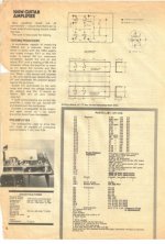
Do you mean the one in Audio Projects from Electronics Today International Volume 1?
There is a 100 watts/4 ohms guitar amp in that. My copy is a little yellow with age but it should scan OK.
mjona
Yes I believe that is the article. I will recognize it when I see it. If you could do both a dark and light scan or grey scale scan that would be most appreciated.
If you could also scan the subject Project Listing as well - as I recall another project in that; that I used in my original amp. I will know it when I see the article. Email me directly with the article. My address is at the bottom of this post.
Cheers - Kimbal
dear kimbal and majona,Yes I believe that is the article. I will recognize it when I see it. If you could do both a dark and light scan or grey scale scan that would be most appreciated.
If you could also scan the subject Project Listing as well - as I recall another project in that; that I used in my original amp. I will know it when I see the article. Email me directly with the article. My address is at the bottom of this post.
Cheers - Kimbal
if you have this article give me also.i have only misprint type of paper which is destroyed in flood.thanks with warm regard masood
my emails are
khan.shahid251@gmail.com
alvi.masood251@gmail.com
Last edited:
Hi Kimbal,
Good story! I didn't build any monster amps in the 70's, but I did build the Playmaster 138, Playmaster twin 25, my own version PCB of the Playmaster 200W MOSFET (3 channel, L, R & SW) tightly fitted in a 3U rack case, and ETI-466 "The Brute" 300W@4Ohm 2xMJ15003/4 as a bigger SW amplifier (published ETI Feb 1980 & see Paul Cambie's web site), also in a 3U rack case with fan. Lots of other miscellaneous amplifiers were also built.
Glenn
Fellow Melbourne-ite
Remember ANTS ?
dear balerit,
thanks to give link.but there is not pcb and asebelled kits,wiring etc.thanks with warm regard your ever masood
ETI 413 Article
Hi my first post here possibly..
Found this article here
Tuac Amplifier modules - Page 7 - UK Vintage Radio Repair and Restoration Discussion Forum
and thought as its as rare as hens teeth worth a repost.
And yes I had one brought to me with a leg broken on the BD139 !!
What a mess! It had been spray painted matt black and I really wasn't sure if it was worth repairing. Replaced the transistor and "hey presto" the thing sprang into life ! ! !
So thought I had better check the bias which is why I found this post and later the one at Vintage Radio Net.
Wonder how many flash bang wizz amps of today will still be hanging in .......in 40 years time?
Cheers All !
Attachments
They were surprisingly reliable. A friend built a pair back in 1973 and used them as PA amplifiers driving 10"x 4 speaker towers. As you see, no protection of any kind and his were driven by an equally basic, 4 channel, 5 x JFET DIY mixer. They played recorded music at clipping level, week in-week out for years without need for repairs.
As in a lot of projects that seem to defy common sense safety guidelines for 2N3055/MJ2955 type output stages, the protection secret is the small sized power transformer. The rail voltages dive as the load current peaks and the amplifier clips with a gritty sounding reminder that the volume setting is too high for the power available.
The case of course, was just the die-cast Hammond box you see! Some were built in 2U racks but most cast cases I saw were eventually sprayed with black engine paint for appearance and durability. You may think everything about the design is crude by today's standards of super cheap components but in Oz at least, we paid more in dollar terms for components than we do now, 40+ years later and this meant that even a cheap design project like this was unaffordable to the average guy. Times change, thankfully")
As in a lot of projects that seem to defy common sense safety guidelines for 2N3055/MJ2955 type output stages, the protection secret is the small sized power transformer. The rail voltages dive as the load current peaks and the amplifier clips with a gritty sounding reminder that the volume setting is too high for the power available.
The case of course, was just the die-cast Hammond box you see! Some were built in 2U racks but most cast cases I saw were eventually sprayed with black engine paint for appearance and durability. You may think everything about the design is crude by today's standards of super cheap components but in Oz at least, we paid more in dollar terms for components than we do now, 40+ years later and this meant that even a cheap design project like this was unaffordable to the average guy. Times change, thankfully
- Status
- This old topic is closed. If you want to reopen this topic, contact a moderator using the "Report Post" button.
- Home
- Amplifiers
- Solid State
- Can anyone help with an old ETI magazine article ??