Hi all,
Many people praises Mosfets for OP stages.
Let's speak about a middle size PA amplifier (500-1000 W on 4 Ohm).
Are there any advantages to use Vertical Mosfets in a class AB design over BJTs?
Please let Laterals and other exotic parts out of this discussion.
I see some disadvantages:
Less watts due to bigger losses, more difficult to select perfectly paired devices, more HF stability issues.
Also there is not perfectly P-N part equivalence, but for this a "quasi" topology would probably do for PA use.
Part cost is about the same as good BJTs , depending where you buy them.
On the good side it seems Vertical MOS are more "robust". But since they are also prone to thermal runaway I would like to hear more practical experience about that. What I can se is that there are parts rated for very high currents and with decent SOA, but the power is ultimately limited by the package, so it seems you will have to use the same number of devices as BJTs at the end.
So, why MOS?
You might want to read this thread http://www.diyaudio.com/forums/solid-state/101745-bob-cordell-interview-bjt-vs-mosfet.html
I personally prefer them (hexFets) in simple circuits with high bias
I personally prefer them (hexFets) in simple circuits with high bias
There is no doubt that good performance can be obtained using vertical mosFET output stages.
These have become ever more popular due to the relatively cheap availability of switching mosFETs.
For PA duty, I would tend to go towards cheapest, rather than best.
For best, I would aim for mosFET driver, feeding a wide bank of BJTs.
These have become ever more popular due to the relatively cheap availability of switching mosFETs.
For PA duty, I would tend to go towards cheapest, rather than best.
For best, I would aim for mosFET driver, feeding a wide bank of BJTs.
For best, I would aim for mosFET driver, feeding a wide bank of BJTs.
Wow, that you are telling this, takes all my doubts away to go further with a current new amp design, in which I'm driving Sanken 2922/1216 with 2sk2013/2sj313 mosfet's.
Hehe like my BIGBT-sFor best, I would aim for mosFET driver, feeding a wide bank of BJTs.

With EC, matching P-ch to N-ch is not so much of an issue if you choose two that have relatively equal transconductance. The Rds-on figure is irrelevant for this type of application. The P-ch will have a greater Ciss than the N-ch for equal Gm, but if you use a complementary source follower Ciss is not so much of a problem because it is bootstrapped from the output node. It is important to clamp the gate drive so it does not excessively charge the gates when driven above Vd. Don't forget the gate source Zener protection diodes. Coss is more of an issue.
I am fond of the planer stripe architecture. I find them to be a bit more robust and able to take significant abuse when used for analog applications. Stay away from Trench fets, U-fets, and other types with similar architecture. They are not suitable for analog apps. Vds breakdown is not so consequential as long as it is higher than 2Vdd. For example, FQP44N10 (Vds=100V)and FQP47P06 (Vds=60V) would be good complements for rails +/-25V or less, Gm is similar. Local frequency compensation is a must and a small value gate Zobel from gate to drain as close to the device pins after the gate stopper resistor on each device is a great way to dampen the tanking components, those being the internal capacitances and lead/bonding wire inductances.
Although these devices create lots of distortion due to the exponential transfer (great for switching apps tho") ) there is no reason why a class AB Hi-Fi amplifier cannot be made. Bob's paper is a great example. In fact, I use the concepts discussed to build this amp. It has shown me and to my surprise how rugged those devices can be made to be. I recommend you use about 20mA per device pair in the driving stage. This assures the drivers always remain in class A operation during charging/discharging of the gates. Bias current should be at least 100-200mA. This helps to traverse the low Gm operating region at around cut-off. Because of the low Gm region at around bias, vertical mosfets are more forgiving as far as thermal compensation is concerned but they still require it. Here is another amp I previously made using the planer stripe vertical mosfets.
) there is no reason why a class AB Hi-Fi amplifier cannot be made. Bob's paper is a great example. In fact, I use the concepts discussed to build this amp. It has shown me and to my surprise how rugged those devices can be made to be. I recommend you use about 20mA per device pair in the driving stage. This assures the drivers always remain in class A operation during charging/discharging of the gates. Bias current should be at least 100-200mA. This helps to traverse the low Gm operating region at around cut-off. Because of the low Gm region at around bias, vertical mosfets are more forgiving as far as thermal compensation is concerned but they still require it. Here is another amp I previously made using the planer stripe vertical mosfets.
I am fond of the planer stripe architecture. I find them to be a bit more robust and able to take significant abuse when used for analog applications. Stay away from Trench fets, U-fets, and other types with similar architecture. They are not suitable for analog apps. Vds breakdown is not so consequential as long as it is higher than 2Vdd. For example, FQP44N10 (Vds=100V)and FQP47P06 (Vds=60V) would be good complements for rails +/-25V or less, Gm is similar. Local frequency compensation is a must and a small value gate Zobel from gate to drain as close to the device pins after the gate stopper resistor on each device is a great way to dampen the tanking components, those being the internal capacitances and lead/bonding wire inductances.
Although these devices create lots of distortion due to the exponential transfer (great for switching apps tho
) there is no reason why a class AB Hi-Fi amplifier cannot be made. Bob's paper is a great example. In fact, I use the concepts discussed to build this amp. It has shown me and to my surprise how rugged those devices can be made to be. I recommend you use about 20mA per device pair in the driving stage. This assures the drivers always remain in class A operation during charging/discharging of the gates. Bias current should be at least 100-200mA. This helps to traverse the low Gm operating region at around cut-off. Because of the low Gm region at around bias, vertical mosfets are more forgiving as far as thermal compensation is concerned but they still require it. Here is another amp I previously made using the planer stripe vertical mosfets.
Last edited:
Sorry for the late answer, there is so much to learn!
I am reading the Bob's paper as well.
For AndrewT: Thanks for the hints.
So, forgetting price and sound quality, what you think about reliability?
Do VMOS bring any advantage over good (say ONsemi stuff) BJTs?
CBS 240:
Thanks a lot for the very useful infos.
However:
Could you please quote some part number in the, say, 250W package range?
And, BTW, your proposed 25 V rail value is too less in PA.
I am looking at something that can do 200V Vds at least....
I am reading the Bob's paper as well.
For AndrewT: Thanks for the hints.
So, forgetting price and sound quality, what you think about reliability?
Do VMOS bring any advantage over good (say ONsemi stuff) BJTs?
CBS 240:
Thanks a lot for the very useful infos.
However:
Agree, but some said complementar pairs do not even have the same Id Max. That's why the Quasi way looked simpler to me.With EC, matching P-ch to N-ch is not so much of an issue if you choose two that have relatively equal transconductance. The Rds-on figure is irrelevant for this type of application. The P-ch will have a greater Ciss than the N-ch for equal Gm, but if you use a complementary source follower Ciss is not so much of a problem because it is bootstrapped from the output node. It is important to clamp the gate drive so it does not excessively charge the gates when driven above Vd. Don't forget the gate source Zener protection diodes. Coss is more of an issue. .
Would you elaborate on why you like more planar?I am fond of the planer stripe architecture. I find them to be a bit more robust and able to take significant abuse when used for analog applications. .
Could you please quote some part number in the, say, 250W package range?
And, BTW, your proposed 25 V rail value is too less in PA.
I am looking at something that can do 200V Vds at least....
Paraphrasing Nelson Pass: MOSFETs are generally much faster than BJTs, so they can tolerate more feedback without increased TIM, so despite initially worse distortion they can end up better after feedback is applied.
And who said MOSFETs are prone to thermal runaway? My MOSFET PA amps only have some protection at the power supply; if you short the output the house lights dim, the fans go on high, the shorted speaker wire strand glows red and burns out and then the house light come back up and the fans quiet down and the show goes on LOL. And I hear that if I ever do blow one, they don't tend to put the DC rail thru your speakers.
And who said MOSFETs are prone to thermal runaway? My MOSFET PA amps only have some protection at the power supply; if you short the output the house lights dim, the fans go on high, the shorted speaker wire strand glows red and burns out and then the house light come back up and the fans quiet down and the show goes on LOL. And I hear that if I ever do blow one, they don't tend to put the DC rail thru your speakers.
Yes, and Yes.Have you looked at Quasi's Threads?
Or Apex's Threads?
There are some mighty high power amps in there.
While Quasi seems to prefer the MOS, for what I gathered from Apex he abandoned MOS for BJTs in his excellent PA designs.
So the question is still open, if the VMOS brings any real advantage over MODERN BJTs. Myself I have long term experience of BJT high power stuff
(on the 1-2 kW range, with TO3s) but none with MOS, so I am trying to make up my mind before eventually starting to play with them (it is going to be an expensive game).
Paraphrasing Nelson Pass: MOSFETs are generally much faster than BJTs, so they can tolerate more feedback without increased TIM, so despite initially worse distortion they can end up better after feedback is applied.
And who said MOSFETs are prone to thermal runaway? My MOSFET PA amps only have some protection at the power supply; if you short the output the house lights dim, the fans go on high, the shorted speaker wire strand glows red and burns out and then the house light come back up and the fans quiet down and the show goes on LOL. And I hear that if I ever do blow one, they don't tend to put the DC rail thru your speakers.
Are you speaking about Laterals or Verticals? Simmetric or quasi?
And, BTW, while your assertions are surely valuable and condivisible on the most part, for my experience the failure mode of any semiconductor that I have seen is SHORT. They will eventually go open AFTER, due to the junction sublimation for the extremely high temperature. But in case you have a speaker connected and not a cable short, that can be too late.
Last edited:
So the question is still open, if the VMOS brings any real advantage over MODERN BJTs. Myself I have long term experience of BJT high power stuff
(on the 1-2 kW range, with TO3s) but none with MOS, so I am trying to make up my mind before eventually starting to play with them (it is going to be an expensive game).
I don't think VMOS will have any real advantage over modern BJTs in class-B.
If you're after a good sound, mosfet or bjt, then no quasi output. With VMOS you are (I guess) left with IRFP240/9240 (I haven't seen complementary part for IRFP460). They are high power, good sounding, probably the most suitable. You can try them in simulation before playing in expensive game.
With the VMOS you will want to use higher power rail. Soundwise, there will be differences. But most of the time, imo, the ones with higher transconductance will win most ears.
If you are familiar with (listening) amplifier topologies, familiar with the output devices and have seen amplifier performance in simulator, I believe you will know the sound of the amp before you build them. So, even if I prefer BJT, I suggest you try VMOS first, at least in simulator.
No, I am not after good sound. I am after reliabilty, ruggedness.I don't think VMOS will have any real advantage over modern BJTs in class-B.
If you're after a good sound, mosfet or bjt, then no quasi output. With VMOS you are (I guess) left with IRFP240/9240 (I haven't seen complementary part for IRFP460). They are high power, good sounding, probably the most suitable. You can try them in simulation before playing in expensive game.
And I am sorry there is no simulator for this (at least at my budget).
So here I am , trying to gather experience from the valuable people of this forum.
The FDL100N50 device looks very interesting. However, I guess, that for linear applications, the package is the limiting factor.I am fond of the planer stripe architecture. .
So, if the package cannot dissipate more than 250W (already a hard assumption with a plastic TO264) I might need at least 4 devices per side to be safe. Also I guess this device is made of Unobtanium, seing how it is priced.
At the end probably 4 x 40N50 x2 will do the the job wonderfully.
A couple of MJL4281/4302 (high hfe, high Ft) will do the driver alone.
Last edited:
If you are familiar with (listening) amplifier topologies, familiar with the output devices and have seen amplifier performance in simulator, I believe you will know the sound of the amp before you build them.
WOW, that's what I needed.
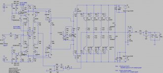
So Jay, can you tell me what your personal idea is of following topology regarding listening impression?
BTW: FET's BOB79 and BOB216 will be 2SK2013/2SJ313. I'm having no spice model from these.
Thanks in advance
Effebi, sorry, this has nothing to do with this thread, I'll keep it short. Or go further with PM.
No, I am not after good sound. I am after reliabilty, ruggedness..
I think it is irrelevant to the amplifying device chosen, no? I mean, for any type of device you can design independent protection schemes for any types of failure.
So here I am , trying to gather experience from the valuable people of this forum.
No need to reinvent the wheel. Steal the best, invent the rest.
I am fond of the planer stripe architecture. I find them to be a bit more robust and able to take significant abuse when used for analog applications.
The primary key to good sound with mosfet is the drive. The planar stripe is easier to drive than IRF or laterals. If everyone know this, I believe there will be more amps built or redesigned using these mosfet.
So Jay, can you tell me what your personal idea is of following topology regarding listening impression?
Your amp doesn't look right, but you should know better, you know electronics better than I do.
1) Bipolar amps have high transconductance. This makes all bipolar amps sound "the same" to my ears. I am not really into bipolar designs, but I think what I want to see with bipolar amps are extreme linearity, with wide bandwidth design. The SC2922 (50MHz) was my favorite. Haven't heard his 60MHz sibling but I couldn't find genuine C2922 locally so I care less about bipolar design.
2) After fast device is chosen, you still need to design the relevant circuit. I think this is very difficult. Not a matter of types of device used, but a matter of how to make it work. I know very little, but I smell something wrong in your approach.
3) Your mosfet looks like having insufficient drive. You may need to cascode it or do something else about it (don't ask me how to do that
). You may add complexity to drive the mosfet properly but then the mosfet might have no purpose there. I think the question you have to answer is why you need the mosfet driving the bipolar (especially when 4 pairs can be easily be driven with MJE340 without problems) in the first place.I can go on and on, but I think proper design will determine how a bipolar amp will sound. I guess a mosfet driver will only alter the sound when it cannot do what it is supposed to do.
I think the question you have to answer is why you need the mosfet driving the bipolar (especially when 4 pairs can be easily be driven with MJE340 without problems) in the first place.
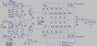
Just for teaser, let's design a fast, high slew rate bipolar amp...
1) You want a fast output bjt for sure. So 2SC2922 (50MHz) is the correct choice. You may not need base resistors.
2) You need a fast driver also. MJE340 is too slow, cannot do the job. Fast bjt drivers are in TO-9. Do they have enough power for the job? Take the KSC part as candidate, or mosfet (but be prepared to solve more issues) as another candidate.
3) You need high rail voltage for the front end. You like JFET sound? JFET is usually chosen because of the effect of its low noise property. But hey, you have noisy current source! LTP cascode is a must. Is that a suitable bipolar you have there?
4) Why the noisy MJE340 in the LTP current source? Are you planning very high bias for the front end? I don't think you can easily achieve high slew rate amp with very high bias at the LTP. You will run out of options to design a proper VAS/driver. Or wait, may be you have new generation mosfets and some smart tricks????
In other words, this is a project for real experts... But it must start with an idea or objective... Sometimes it can be as simple as using certain device (usually mosfet) to induce pleasant harmonics into the circuit.
Thanks Jay,
1) You want a fast output bjt for sure. So 2SC2922 (50MHz) is the correct choice. You may not need base resistors.
Main reason wy I want to use them is that I bought a year ago 16 pairs of these. There specs where telling me to buy them and use them for a future project.
2) You need a fast driver also. MJE340 is too slow, cannot do the job. Fast bjt drivers are in TO-9. Do they have enough power for the job? Take the KSC part as candidate, or mosfet (but be prepared to solve more issues) as another candidate.
Well, I definetely would like to use mosfet's (2SK2013/2SJ313) as drivers. It's just looks right in my eyes to use FET's as drivers instead of a 2EF of 3EF OPS.
And I think mosfet's will be fast enough?
3) You need high rail voltage for the front end. You like JFET sound? JFET is usually chosen because of the effect of its low noise property. But hey, you have noisy current source! LTP cascode is a must. Is that a suitable bipolar you have there?
If I like Jfet sound? I hope to find that out in the future. Have some 389/109 pairs in stock.
The CCS is used for the zeners as cascode voltage. The 2SC3381/2SA1349 are made by Toshiba for cascode purposes. But, there dissipation is to low in this design.
4) Why the noisy MJE340 in the LTP current source? Are you planning very high bias for the front end? I don't think you can easily achieve high slew rate amp with very high bias at the LTP. You will run out of options to design a proper VAS/driver. Or wait, may be you have new generation mosfets and some smart tricks????
Bias front end: +-75% of IDSS of JFET ==> 4-5ma
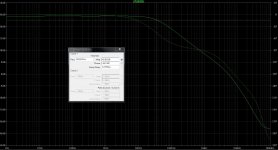
In general: I would like to design an amp with an open loop bandwidht of approx 40khz and using as less as possible miller capacitance (this means not to high gain).
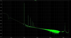
I will be focussing at the FFT spectrum. I hope to achieve mainly 2nd and 3th harmonics.
So far, this is the best amp I ever sim'med (only reference I'm having). This VAS wsas a miracle in this design for the above points. Vas is running at approx 8ma.
1) You want a fast output bjt for sure. So 2SC2922 (50MHz) is the correct choice. You may not need base resistors.
Main reason wy I want to use them is that I bought a year ago 16 pairs of these. There specs where telling me to buy them and use them for a future project.
2) You need a fast driver also. MJE340 is too slow, cannot do the job. Fast bjt drivers are in TO-9. Do they have enough power for the job? Take the KSC part as candidate, or mosfet (but be prepared to solve more issues) as another candidate.
Well, I definetely would like to use mosfet's (2SK2013/2SJ313) as drivers. It's just looks right in my eyes to use FET's as drivers instead of a 2EF of 3EF OPS.
And I think mosfet's will be fast enough?
3) You need high rail voltage for the front end. You like JFET sound? JFET is usually chosen because of the effect of its low noise property. But hey, you have noisy current source! LTP cascode is a must. Is that a suitable bipolar you have there?
If I like Jfet sound? I hope to find that out in the future. Have some 389/109 pairs in stock.
The CCS is used for the zeners as cascode voltage. The 2SC3381/2SA1349 are made by Toshiba for cascode purposes. But, there dissipation is to low in this design.
4) Why the noisy MJE340 in the LTP current source? Are you planning very high bias for the front end? I don't think you can easily achieve high slew rate amp with very high bias at the LTP. You will run out of options to design a proper VAS/driver. Or wait, may be you have new generation mosfets and some smart tricks????
Bias front end: +-75% of IDSS of JFET ==> 4-5ma
In general: I would like to design an amp with an open loop bandwidht of approx 40khz and using as less as possible miller capacitance (this means not to high gain).
I will be focussing at the FFT spectrum. I hope to achieve mainly 2nd and 3th harmonics.
So far, this is the best amp I ever sim'med (only reference I'm having). This VAS wsas a miracle in this design for the above points. Vas is running at approx 8ma.
Attachments
Last edited:
- Status
- This old topic is closed. If you want to reopen this topic, contact a moderator using the "Report Post" button.
- Home
- Amplifiers
- Solid State
- Vertical MOSFETs for a PA amplifier OP