Why current drive?
http://www.essex.ac.uk/csee/researc...J12 Distortion reduction MC current drive.pdf
Look at the massive reduction in distortion!
A disadvantage of current drive is a loss of damping at the resonant frequency of the speaker. Nelson Pass solution to this was a parallel network but if you think about this it's dumb. As the impedance of the source becomes low at resonance therefore making it a voltage output amplifier at resonance loosing the distortion advantage in the most critical region. I would like to dismiss all discussion of parallel networks as they result in only a high output impedance voltage amplifier. The better way appears to be motional feedback which has good results in the above paper. I have also found another paper where more practical circuits are explored:
http://www.essex.ac.uk/csee/researc...bdocs/J14 Mills-Hawksford power amplifier.pdf
Any thoughts on using duel voice coil woofers to avoid having to take woofers apart to get sensing coil?
Anyway I am wondering if anyone has built or is operating a system with transconductance power amplifiers and would like to utilise the community to search out as much info as possible on the subject as they seem quite exciting!
I did some more reading about the lack of damping a resonance issue and it appears that the primary problems are parameter shifts in drivers causing equalisation without feedback to have errors due to parameter shift hence the need for a closed loop. This is also Another reason not to use a parallel network; look at the shifts in fs and q of the system in these tests:
Zaph|Audio
It seems the best way of measuring driver position would be some kind of laser measurement device. My idea for this would to be measure the velocity of the cone via the Doppler shift on a modulating square wave on the laser. I don't know anything about lasers though or how fast photo detectors can go...
Hi Kipman,
A couple of points on current drive:
1) look at fig. 14 a. and b. of hawksfords paper and see how current drive wreaks heavoc with the frequency response of a driver;
2) somewhere in the paper hawksford refers to the problem voltage drive may have with xovers. True, there are interactions, but try to design an xover for a current drive amp! A perfect one current drive amp would have an infinite output impedance, which would become part of the xover. So where do you go from there?
And on motional feedback in any way shape or form:
Imho it is overdoing it, because the compensation which has to be made on the low end (where mfb works) is pretty straightforward. The Linkwitz transform, which compensates for the predictable 12dB downslope of a sealed enclosure below F-3dB, therefore does the trick just as well, with much less complexity.
vac
vac
Last edited:
From the mechanical-electrical analogy it is immediately obvious that electrodynamic speakers are current driven. Using a current source amplifier as drive requires a compensation of mass compliance ... i.e. of all mechanical properties of the speaker.
The attachment shows a circuit patented by AES for vented woofers, which is however
applicable to midrange and tweeter as well. The elements at the output of the power amp are the electrical representation of a vented woofer.
Thus current driving makes only sense for active speakers.
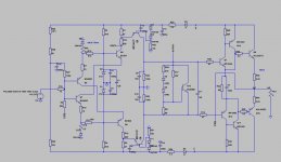
The attachment has a circuit of an inverting power amp.
The attachment shows a circuit patented by AES for vented woofers, which is however
applicable to midrange and tweeter as well. The elements at the output of the power amp are the electrical representation of a vented woofer.
Thus current driving makes only sense for active speakers.
The attachment has a circuit of an inverting power amp.
Attachments
The proper solution to flat FR is to build a speaker with either flat impedance, or a speaker with an impedance curve that is complmentary to its FR.
An aperiodic box or a very heavily stuffed sealed box with a low Qm driver. Passive XOs should also be avoided.
EQ in the amp can also deal with some of the problem.
dave
An aperiodic box or a very heavily stuffed sealed box with a low Qm driver. Passive XOs should also be avoided.
EQ in the amp can also deal with some of the problem.
dave
Hi Kipman,
A couple of points on current drive:
1) look at fig. 14 a. and b. of hawksfords paper and see how current drive wreaks heavoc with the frequency response of a driver;
2) somewhere in the paper hawksford refers to the problem voltage drive may have with xovers. True, there are interactions, but try to design an xover for a current drive amp! A perfect one current drive amp would have an infinite output impedance, which would become part of the xover. So where do you go from there?
And on motional feedback in any way shape or form:
Imho it is overdoing it, because the compensation which has to be made on the low end (where mfb works) is pretty straightforward. The Linkwitz transform, which compensates for the predictable 12dB downslope of a sealed enclosure below F-3dB, therefore does the trick just as well, with much less complexity.
vac
vac
The motional feedback is to modify the parameters of the speaker such that the high Q resonance (that causes frequency response problems) is damped by the motional feedback. Simple EQ of this peak is subject to error due to parameter shift of the driver with time/temp. In the Hawksford paper their Monte Carlo sim of this estimates 2dB of error at resonance using EQ. Simple EQ is defiantly the way to initially approach the problem but not a final solution.
As for crossovers and EQ; I run fully active systems almost exclusively using DSP crossovers. I have a mini-dsp on my bedroom system and use KX-project drivers on the communal TV computer. I'm also a pretty good at digital hardware and have taken many advanced DSP courses so would probably approach this problem by doing all the processing in the digital domain.
The proper solution to flat FR is to build a speaker with either flat impedance, or a speaker with an impedance curve that is complmentary to its FR.
An aperiodic box or a very heavily stuffed sealed box with a low Qm driver. Passive XOs should also be avoided.
EQ in the amp can also deal with some of the problem.
dave
yup... certainly a valid approach. I like sealed boxes however and that usually means a high Q driver. Motional feedback should allow the usage of pretty much any bass driver with a given cone area and excursion capability to work in any sealed box as long as the power is kept under the limit of the driver.
From the mechanical-electrical analogy it is immediately obvious that electrodynamic speakers are current driven. Using a current source amplifier as drive requires a compensation of mass compliance ... i.e. of all mechanical properties of the speaker.
The attachment shows a circuit patented by AES for vented woofers, which is however
applicable to midrange and tweeter as well. The elements at the output of the power amp are the electrical representation of a vented woofer.
Thus current driving makes only sense for active speakers.
The attachment has a circuit of an inverting power amp.
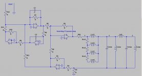
At the moment I quite like the look of the topology with current mirrors driving the load. I will have to think about a sensible way of making a current multiplying mirror out of discreet parts though. Some kind of opamp based Vgs control on the 2nd mirror transistors probably. If I was only making it on a chip it would be so easy as I could just make the transistors bigger!
From the mechanical-electrical analogy it is immediately obvious that electrodynamic speakers are current driven. Using a current source amplifier as drive requires a compensation of mass compliance ... i.e. of all mechanical properties of the speaker.
The attachment shows a circuit patented by AES for vented woofers, which is however
applicable to midrange and tweeter as well. The elements at the output of the power amp are the electrical representation of a vented woofer.
Thus current driving makes only sense for active speakers.
The attachment has a circuit of an inverting power amp.
Hi Hafran,
That seems to be a very creative solution for a basic problem with current drive. However, I see a problem with this approach.
The mechanical properties of any speaker are not linear, both at different power settings, and in time with aging etc. The compensation circuit would have to dynamically change when these driver parameters change, otherwise the compensation parameters will no longer match those of the driver.
Anyways, I would be interested to know if this setup has been implemented somewhere, and if results have been published,
vac
Putting the speaker (woofer anyway) in the feedback loop was done in 1972? L. W. Erath of Houston Texas did it in commercial speakers. I owned a pair of LWE III two way sealed speakers where some Jones plugs were installed in my dynakit ST70 amp to put the speaker sensor in the amp feedback loop. The speakers had impressive bass for 10" woofers, and not buzz, buzz, buzz either. Considering the technology breakthroughs in 1972, I imagine he was using aluminum reflective tape and lights and new analog sensors available then. Woofer excursion as about 1" on Tommy Boyce & Bobby Hart 45's. (ATCO 45's had very high velocity then).I
It seems the best way of measuring driver position would be some kind of laser measurement device. My idea for this would to be measure the velocity of the cone via the Doppler shift on a modulating square wave on the laser. I don't know anything about lasers though or how fast photo detectors can go...
One speaker finally died due to an open tweeter, not the woofer. Then my father threw them away while I was in the Army. Don't know what was on the back of the woofer.
Last edited:
Philips did it in the 70-ies with a piezo-electric element inside the dustcap. The voltage generated by the piezo was representing speaker acceleration, and they integrated that to get velocity and then again to get position.
This information was used in a feedback system to control the low end.
jan didden
This information was used in a feedback system to control the low end.
jan didden
sure google speaker maker AES .Hi Hafran,
That seems to be a very creative solution for a basic problem with current drive. However, I see a problem with this approach.
The mechanical properties of any speaker are not linear, both at different power settings, and in time with aging etc. The compensation circuit would have to dynamically change when these driver parameters change, otherwise the compensation parameters will no longer match those of the driver.
Anyways, I would be interested to know if this setup has been implemented somewhere, and if results have been published,
vac
AES had this compensation patented and is about to implement the method
on midrange in a 3 way. The trick is as simple as possible, the output impedance of the driver mirrors the impedance of the speaker . This can of course only be accomplished with a transconductance amp.
For long, I could not get any satisfying explanation for the reason why, for the same excursion at a given frequency, a current driven loudspeaker unit generates less distorsion than when voltage driven.
It now seems to me that it's related to the phenomenon known as instability of a driver :
[...]As the coil moves away from the central rest position, the bacl EMF is reduced due to the lowered Bl factor and hence more power [I should say "current"] is drawn from the amplifier (assuming a normal constant voltage source)
Martin Colloms "High Performance Loudspeakers"
Is a driver a device controlled by voltage or by current ?
Both points of view are valid.
Frequency response is usually flatter when voltage driven, and frequency response is the first thing we try to control. Whatever the source impedance, the same voltage at a given frequency across a driver will give the same output (neglecting temperature effects). This is the base for the design of passive crossovers and transforms, and then, the driver is considered as a voltage controlled device.
However, if we seek causes of non-linearities of a driver, it would be easier to observ its behaviour with a current source which is related to the force applied to the cone, and to consider it as a current controlled device.
An article of combination of a current controlled driver and acceleration MFB, I am not aware of an application :
Greiner, Travis et Sims :
"Loudspeaker Distortion Reduction
JAES Volume 32 Issue 12 pp. 956-963; December 1984
Nonlinear distortion and frequency response aberrations are the major weaknesses of low-frequency loudspeaker systems. A multiple-loop feedback system is presented that deals effectively with both of these problems. The feedback system, utilizing current and velocity feedback, also decouples the system Q factor from enclosure and driver parameters. A theoretical analysis is presented which has been the basis for several successful system designs. Extensive data on several practical systems have been taken to show the usefulness of this approach. Data for two of these systems are given here.
Authors: Greiner, R.A.; Sims, Jr., Travis M."
- Status
- This old topic is closed. If you want to reopen this topic, contact a moderator using the "Report Post" button.
- Home
- Amplifiers
- Solid State
- Lets talk about transconductance amplifiers