Hi all,
I've got a Mackie SRM450 active PA speaker which about 2 years ago blew it's fuse. I narrowed the problem down to being the main power transformer, by the fact that with the secondary side disconnected from the board, it still blew the fuse, but with the primary side disconnected, it didn't. I enquired about a new transformer, got told a price, picked myself up off the floor, and forgot about it for the next two years
Last week I decided that it was taking up too much space in my garage to justify not fixing it, so I ordered the transformer, put it in, and hey presto, it lived! I went into the next room to find somebody to share in my excitement, when I heard BOOM, and returned to find a room full of smoke and a smell not dissimilar to an extended fireworks display.
Turns out one of the main power filter capacitors had blown (and taken out the fuse once more, albeit not quite fast enough). So my next move is to replace all four filter caps, but I thought I should see if I can't get some answers to some niggling questions first...
-Is it likely that the capacitor just blew from having no use for couple of years and then being dragged out of retirement?
-Is it likely (or possible) that the faulty capacitor took out the original transformer?
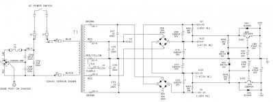
-Is there anything else I should be replacing (or testing) while I'm at it? Anything that may have been damaged in the process, or something that may actually be the root cause of both the transformer AND the capacitor? I'll attach the relevant part of the schematic below.
I wasn't running it hard when it blew - it was in my lounge room, so it was actually at a very low volume, especially considering the use my SRM450's usually get. The cap that let the smoke out was C170.
Thanks guys, I appreciate any insights")
I've got a Mackie SRM450 active PA speaker which about 2 years ago blew it's fuse. I narrowed the problem down to being the main power transformer, by the fact that with the secondary side disconnected from the board, it still blew the fuse, but with the primary side disconnected, it didn't. I enquired about a new transformer, got told a price, picked myself up off the floor, and forgot about it for the next two years
Last week I decided that it was taking up too much space in my garage to justify not fixing it, so I ordered the transformer, put it in, and hey presto, it lived! I went into the next room to find somebody to share in my excitement, when I heard BOOM, and returned to find a room full of smoke and a smell not dissimilar to an extended fireworks display.
Turns out one of the main power filter capacitors had blown (and taken out the fuse once more, albeit not quite fast enough). So my next move is to replace all four filter caps, but I thought I should see if I can't get some answers to some niggling questions first...
-Is it likely that the capacitor just blew from having no use for couple of years and then being dragged out of retirement?
-Is it likely (or possible) that the faulty capacitor took out the original transformer?
-Is there anything else I should be replacing (or testing) while I'm at it? Anything that may have been damaged in the process, or something that may actually be the root cause of both the transformer AND the capacitor? I'll attach the relevant part of the schematic below.
I wasn't running it hard when it blew - it was in my lounge room, so it was actually at a very low volume, especially considering the use my SRM450's usually get. The cap that let the smoke out was C170.
Thanks guys, I appreciate any insights
Attachments
That's why clever guys invented DMMs. Before that people just plugged their gear in mains to check what would happen. I hope your new transformer survived.
I don't know the age of the amp but I would first check all parts in the power supply if they're OK, replace what's faulty and then replace all electrolytic caps anyway. Old news butt the caps are the most likely source for errors as they dry out and/or crappy quality is used etc. but repeating well known stuff is not necessary.
10.000 uF 50V won't hurt if they fit.
Last edited:
Very possible defective caps could damage (overheat) the transformer if they were drawing excess leakage current. You would know by the caps getting hot.
If there is any doubt then replace them. Transformers stand a lot of abuse. If they are overloaded it is the heat that kills them by melting insulation on the windings.
If there is any doubt then replace them. Transformers stand a lot of abuse. If they are overloaded it is the heat that kills them by melting insulation on the windings.
50 V caps having to withstand 47.5 V idle... that's kinda tight in the long run. (Even if ratings for electrolytics tend to be "WV" = working voltage, not abs max.) It's not unusual for electrolytics to develop spots in the dielectric that cannot withstand full rated voltage in old age. This can lead to significant current flowing, and it's quite possible that this eventually resulted in the demise of the original xmfr.
I'd recommend 6800 µF 63 V types.
Maybe fashion a bulb tester, too.
I'd recommend 6800 µF 63 V types.
Maybe fashion a bulb tester, too.
The synchronicity of this is startling. I began troubleshooting one of my pair of 450s Friday night after it had developed a hum problem. When I pulled the amp plate out, C170 & C171 (the 45V rail caps--the middle pair of the four-cap column) were slightly, but obviously, bulging on top.
The major limitation here are the cap diameters, and the clearance height between the top of the board and the cabinet recess the amp module fits into. There's 47mm clearance between the surface of the board and the cabinet wall. The stock 6800uF 50V 85-degree caps measure 25x42mm.
I put in some time yesterday running down replacement candidates. I started out wanting to install 10,000uF 63V 105-degree devices, but kept coming up against the very real physical limitations of this application.
What I finally decided on are some Cornell Dubilier 10,000uF 50V 85-degree snap-ins. 10-week lead time from Mouser, but I'm willing to wait. These are 25x40mm in CDE's datasheet (not "25.4mm" as Mouser declares on their product page).
If you want something right now, Mouser has stock on the 6,800uF 50V versions of the above. At 25x30mm, they'll fit easily.
If it's any help to you, mine still has the sticker on top with the mackie part number...they'll probably sting you for them but they'll fit
I'm thinking a light bulb tester is a good idea too, but unfortunately for me, a genius politician who obviously has supreme knowledge on things like this outlawed incandescent light globes around two years ago on the grounds that they're not eco-friendly And believe me, I tried for days on end to find a way to get some for another project, and it was dead ends all round. Does anyone know if any other type of globe will work the same? I know compact fluro's/LED won't work, but what about the halogen style ones?
I'm thinking a light bulb tester is a good idea too, but unfortunately for me, a genius politician who obviously has supreme knowledge on things like this outlawed incandescent light globes around two years ago on the grounds that they're not eco-friendly
And believe me, I tried for days on end to find a way to get some for another project, and it was dead ends all round. Does anyone know if any other type of globe will work the same? I know compact fluro's/LED won't work, but what about the halogen style ones?The halogen replacements for the incandescent should work.
They are both tungsten filament and both have the desired PTC characteristic.
I have not bought any of these halogen replacements. They are charging ~£2.50 each, whereas the old style were ~£0.50 each.
Do you have any working "old" incandescent bulbs around the house/in the garage/in the loft?
They are both tungsten filament and both have the desired PTC characteristic.
I have not bought any of these halogen replacements. They are charging ~£2.50 each, whereas the old style were ~£0.50 each.
Do you have any working "old" incandescent bulbs around the house/in the garage/in the loft?
So did the hum stop?
Just pulled apart my 1st gen srm 450 due to humming when using microphone, Noticed that those caps are slightly bulged on mine as well. Wondering how the replacements worked out?The synchronicity of this is startling. I began troubleshooting one of my pair of 450s Friday night after it had developed a hum problem. When I pulled the amp plate out, C170 & C171 (the 45V rail caps--the middle pair of the four-cap column) were slightly, but obviously, bulging on top.
The major limitation here are the cap diameters, and the clearance height between the top of the board and the cabinet recess the amp module fits into. There's 47mm clearance between the surface of the board and the cabinet wall. The stock 6800uF 50V 85-degree caps measure 25x42mm.
I put in some time yesterday running down replacement candidates. I started out wanting to install 10,000uF 63V 105-degree devices, but kept coming up against the very real physical limitations of this application.
What I finally decided on are some Cornell Dubilier 10,000uF 50V 85-degree snap-ins. 10-week lead time from Mouser, but I'm willing to wait. These are 25x40mm in CDE's datasheet (not "25.4mm" as Mouser declares on their product page).
If you want something right now, Mouser has stock on the 6,800uF 50V versions of the above. At 25x30mm, they'll fit easily.
I'm thinking a light bulb tester is a good idea too, but unfortunately for me, a genius politician who obviously has supreme knowledge on things like this outlawed incandescent light globes around two years ago on the grounds that they're not eco-friendly
Maplin? - The Electronics Specialist still do incandescent bulbs in the UK.
Sorry, compscirunner, only just saw your question.Just pulled apart my 1st gen srm 450 due to humming when using microphone, Noticed that those caps are slightly bulged on mine as well. Wondering how the replacements worked out?
The CDEs worked great. The humming '450 is dead quiet now.
Given the application, and how hot it can get inside that amp compartment on the back of the speaker, I would have gladly traded off the increased capacitance for a part rated at 105-degrees, just for the increased longevity. But I couldn't find them in the necessary form factor.
So I have 450 v1 with the round transformer that blew fuses. I found the output transistors on the LF side were blown. Replaced them first. I do use a light bulb home made current limiting box. The same transistors are getting very hot. When I unplugged the power supply connector to the board the fuse didn't blow. When I plugged it back in the bulb was brightly lit, indicating a large current draw and it would surely blown the fuse. The caps look good and are not hot even tho I suspect one of them when put under the load. I have the schematic trying to work off it to troubleshoot. Any ideas what I should check next? Thanks guys! BTW I get 60 watt and even 100 watts bulbs incandescent from Lowes and sometime the dollar store. I still find them here in Kentucky. Also FYI, I have test equipment DMM, Oscilloscope, Signal generator, capacitance meter, power supply. I do not have an ESR meter.
Last edited:
If transistors are hot, drawing too much current on bulb limiter, and not oscillating, then possibly speaker turn is shorted or wireing to it is shorted. Try running the output instead into an appropriate (4 ohm or 8 ohm) resistor load. Ohmmite 225 W log resistors are the obvious candidates, but at about $30 each, I'd go measuring blown room heater elements (no fan motor) or coffee cup heaters or something cheap. room heaters are always blowing the tip over switch.
You could also put 0.1 ohm 20 w in series with the speaker and measure the voltage across it (current =v/r) About 3 amps per TO3 transistor pair (mj15024/5) , or 2 amps per TO247/263 transistor pair (c5200/a1943) is about max. On a mackie I'd expect the latter, they are cheaply built.
Alternatively, the idle bias control circuit for the output transistors could be out of control. If they are bjt, from base of npn to base of pnp should be about 0.6 v idle, giving about 20-80 ma idle current across the emitter resistors at all times. If the outputs are fets, about 3-5 v idle voltage gate to gate, although I am not expert on fets. Same idle current however. Often idle adjustment pots go open on the wiper, or sense through connectors oxidizes. Oxidized connectors need reseated, idle adjust pots need sprayed out & or replaced with a fixed resistor of appropriate value.
Last edited:
Caco58, if you have the schematic, try measuring the voltage across J21 pins 1 & 2--these pins monitor the voltage drop across the output transistor emitter resistors. R202 is the bias adjustment; turn it fully counter-clockwise to begin.
If you've got a high-bias situation, you don't want to apply power any longer than you have to to get an initial reading. Measure the emitter resistors R152 & R201 before powering on, to be certain they're still the specified 0.22 ohms.
The optimal bias adjustment is for 4 - 4.5 mV across the J21 pins, which represents 9 - 10mA. It might sound low to some, but that's Mackie's spec for the output stage idle current.
If you can't get a proper reading, there's something else wrong, possibly an open transistor in the bias circuit. Did you replace Q18?
- Status
- This old topic is closed. If you want to reopen this topic, contact a moderator using the "Report Post" button.
- Home
- Amplifiers
- Solid State
- Blown power filter cap