Hi folks!
I have been working on the layout of Sir Rod Elliot's Guitar Amplifier.
I built the the power amp module but I am unable to set the quiescent current. On the minimum position of the 4k7 preset, I get the voltage at the collectors of the transistors at around 100mV!!
I also tried changing the pot twice...But it doesn't work....
Rod suggests us to set it at 11mV Which will set the quiescent current at a desirable 22mA.
Also when I run the amplifier, There is distortion and a lot of phasing too.
I don't understand what the problem is :/
It would be really thankful if someone could help me out with this problem
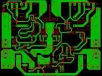
I have attached the layout that I have prepared for the amplifier.
Regards
Brutus
I have been working on the layout of Sir Rod Elliot's Guitar Amplifier.
I built the the power amp module but I am unable to set the quiescent current. On the minimum position of the 4k7 preset, I get the voltage at the collectors of the transistors at around 100mV!!
I also tried changing the pot twice...But it doesn't work....
Rod suggests us to set it at 11mV Which will set the quiescent current at a desirable 22mA.
Also when I run the amplifier, There is distortion and a lot of phasing too.
I don't understand what the problem is :/
It would be really thankful if someone could help me out with this problem
I have attached the layout that I have prepared for the amplifier.
Regards
Brutus
Attachments
Last edited:
Where does the power supply ground (0 V) connect to the circuit?
Where/how does the input signal ground connect to the amplifier ground?
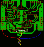
It is done offboard, But I attached the layout with the connections now.
Thanks and Regards
Brutus
Attachments

Not sure if this is your problem, but the ground circuit is not ideal.
See the attachment. The highlighted track is the signal ground and has been modified to not share tracks with 1000 uF caps or the 10 ohm/100 nF zobel network.
How does the speaker return 0.1 ohm resistor connect?
It could be air-wired above or below the circuit board as shown in the attachment.
Can you show a complete diagram or photo, including the power supply?
Attachments
As well as the grounding issues Discrete has noticed, you include fuses yet some parts of the circuit (filter capacitors, input transistor connections) are connected before the fuses. I know this may simplify layout, but it also leaves these parts without the protection of the fuse if one of them was to go bang.
Not sure if this is your problem, but the ground circuit is not ideal.
See the attachment. The highlighted track is the signal ground and has been modified to not share tracks with 1000 uF caps or the 10 ohm/100 nF zobel network.
How does the speaker return 0.1 ohm resistor connect?
It could be air-wired above or below the circuit board as shown in the attachment.
Can you show a complete diagram or photo, including the power supply?
As well as the grounding issues Discrete has noticed, you include fuses yet some parts of the circuit (filter capacitors, input transistor connections) are connected before the fuses. I know this may simplify layout, but it also leaves these parts without the protection of the fuse if one of them was to go bang.
Thanks a lot for your help!
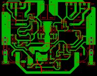
I have modified the layout as per as your suggestions!
discrete : The 0.1E resistor is air-wired on the board!
jackand08 : I just feel so idiotic when you made me realize my mistake!!

Please check out the new layout!
Thanks and Regards!
Brutus!
")
Attachments
Absolutely Great work Mr. Alex!
Your PCBs are just amazing!!
Your PCBs always have that professionalism in them!!
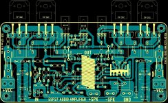
I am able to see some modifications in the amplifier design...can you please explain me the change in the functions due to the modifications?
Thanks once again!
Awaiting your reply
Brutus!!
Your PCBs are just amazing!!
Your PCBs always have that professionalism in them!!
I am able to see some modifications in the amplifier design...can you please explain me the change in the functions due to the modifications?
Thanks once again!
Awaiting your reply
Brutus!!
...... I change, only thermal sensor, from BC 549 to BD 139 and aditional , optional power indicator LED for positive and negative rails . That's all , nothing special , folowed same schematic from ESP site Thanks for your kind words .
I'm glad, to help you, and others . BTW at home my wife call me also Brutus
That was the main reason for making this PCB .....
all the best Alex.
Thanks for your kind words .I'm glad, to help you, and others . BTW at home my wife call me also Brutus
That was the main reason for making this PCB .....
all the best Alex.
...... I change, only thermal sensor, from BC 549 to BD 139 and aditional , optional power indicator LED for positive and negative rails . That's all , nothing special , folowed same schematic from ESP site
I'm glad, to help you, and others . BTW at home my wife call me also Brutus
That was the main reason for making this PCB .....
all the best Alex.
Hehe
Yes, that's what I realised when I was verifying the PCB with the schematic later!
I was so glad that you made a PCB for the project!
Also, for the LED on the negative rail, don't you think that it should be reversed??
Thanks a lot once again!
Brutus!
- Status
- This old topic is closed. If you want to reopen this topic, contact a moderator using the "Report Post" button.
- Home
- Amplifiers
- Solid State
- ESP P27 PCB - Needs checking