Interesting Trannies Nico. Pd is 300mW so on 65V rails with 0.5 LTP current I am already dissipating 300mW, and on high output swing this will peak at over 600mW. (Another reason BTW for the cascodes was to limit the Pd in the diff amps)
Good explanation, thanks Andrew.
The networks between the bases of Q19 and Q28 and their associated rails in the diagrams above are not Miller compensation networks. They are damper networks,
In fact , i was talking in the case where the drivers have
a resistor in serial with the collector , along with the said cap.
I guess this is to mitigate any inductance forming with their collector s
related tracks , provided the resistors are close enough of the drivers.
One of the byproduct is that the collector will have a slight inverted
signal compared to the base , hence a better efficency of the caps
whose value can be reduced.
Andrew,
Kindly try something in simulation and also in practice with your amp by placing a capacitor (experiment with 1 - 100 uF) between the emitters of each differential input pair, before the degeneration resistors.
I found that it creates an AC summing point and suppresses harmonic power density quite substantially.
Last edited:
Wahab quite honestly Ive never seen a comercial design that had to use such "drastic" compensation methods to gain stability with triples. Neither did I have to in any of my designs using triples which is my preferred choice. At max a little miller cap on drivers do the trick. Instead of the caps Ive also made use of small inductor in parralel with the base resistors on ouput transistors for stability.
I prefer to tak about compensation and parasitic prevention as two separate things (which of course they are).
On the Ovation 250, I use a straight RC 'L pad' between the pre-driver emitter and the driver base with the R=27 Ohms and the C (1nF) connected straight to ground. The C can go to ground, or alternatively go to the rails if one assumes the supply is a short to AC. Of course, if you think about the parasitic inductances around the output stage then this is probably a dangerous assumption . . .
The Ovation 250 uses slow 21193/4 devices, BF471/BF472 pre-drivers and 15032/33 for the drivers. Without the 1nF cap to ground, the output stage was unstable and I had HF oscillation. The L pad cure BTW came after some research on the internet, where I picked up a good ap note from Microcap discussing emitter follower stability and how to cure it.
The e-Amp is another kettle of fish, because the output devices are an order of magnitide faster. Couple that to the fact that there are appreciable PCB inductances (similar to the Ovation 250) to contend with (from 2nF to 10nH depending on which output device you look at) and there is every opportunity for problems. I just did not want to take the risk. The amp will work with the removal of the the base stoppers for example, and you can lower the 1nF caps to 220pF and its stable. But, if you leave the caps out you will have problems, and if the caps and the stoppers are removed it can be provoked into HF ringing very easily. The output inductor and the Zobel also keep the operating environment of the output stage consistent at HF in my view in addition to the normal concerns about global stability when driving capacitive loads.
BTW, when I worked on the Ovation 250, one of the things I picked up on was that he speed up cap used across the driver emitter resistor was not good for HF stability and so removed it (I left the speed up cap on the pre-driver stage, but in retrospect do not think it adds any value). On the e-Amp I do not use a speed up cap, but instead rely on the fact that the driver stage current is quite a high, and the driver emitter resistor value low, providing fast turn off. In an exchange on this forum a year or two ago, Bob Cordell also remarked on this point and I was quite pleased to see he had arrived at a similar conclusion.
Last edited:
On the e-Amp I do not use a speed up cap, but instead rely on the fact that the driver stage current is quite a high, and the driver emitter resistor value low, providing fast turn off. In an exchange on this forum a year or two ago, Bob Cordell also remarked on this point and I was quite pleased to see he had arrived at a similar conclusion.
Bob also recommended diode bias with ThermalTrak diodes as the driver emitter load. It looks nice to me, the dynamic resistance can be very low.
Have you looked at this?
Best wishes
David
BTW For a while I have meant to say thanks for the Middlebrook link on your website. Very "low entropy" information.
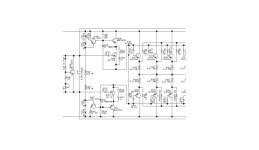
Here is another interesting outputstage. Any comments on the connection of those cascodes ?? In spice its hardly stable but the schematic shown is a real commercial offering.
Can you tell me from which commercial amp this is.
I simmed a few days back something 90% equal to that.
Regarding the cascode connection: they are looking pretty normal to me?
Greetz
Bob also recommended diode bias with ThermalTrak diodes as the driver emitter load. It looks nice to me, the dynamic resistance can be very low.
Have you looked at this?
Best wishes
David
BTW For a while I have meant to say thanks for the Middlebrook link on your website. Very "low entropy" information.
Dave, no - I have not looked at it seriously - something for a future project!
Can you tell me from which commercial amp this is.
I simmed a few days back something 90% equal to that.
Regarding the cascode connection: they are looking pretty normal to me?
Greetz
That is from Inter, I dont know much about them, the scheme is used by accuphase as well since 1990s so there must be advantages except I cant get it stable....yet that is.
The cascodes would be conventional except here the base of the cascode is connected to the sources of the mosfets. Conventional cascode the bases of the cascodes would be connected to each other with no connection to the sources of the mosfets. As it is it looks more like hawksford type cascode connection and probably why it has stability issues.
Hello Andrew,
Thank you very much for taking the time to write up your new amplifier so thoroughly! There's lots of useful ideas in there.
I was just wondering why you chose to use an isolated solid-state relay with optocoupled gate drive rather than the non-isolated design detailed in your separate document on SSLRs? The non-isolated one is cheaper, could I think be optimised for lower power consumption in the gate drive circuit, and is less expensive. What are the advantages of the isolated one?
Also, I have some feedback regarding presentation/grammar/punctuation of your document. Do you mind if I post it here? (Some of the observations and tips may be useful to anyone working on technical documents).
Thanks again,
Harry.
Hello Harry, thanks for your comments.
The control board used in the e-Amp was designed (and the 1st iteration of the PCB's done) before I cooked up the non-isolated version. I am currently working on two new amplifiers that use the non-isolated version.
For the feedback part, please email me at andrewc.russell(at)gmail.com - I welcome your comments.
I hope to do an article sometime and would appreciate the tipsAlso, I have some feedback regarding presentation/grammar/punctuation of your document. Do you mind if I post it here? (Some of the observations and tips may be useful to anyone working on technical documents).
Understandable to want to receive feedback privately but can you post it here after you have read it? Maybe remove any bits you feel sensitive about?For the feedback part, please email me at andrewc.russell(at)gmail.com - I welcome your comments.
Or can Harry post a redacted (I believe that's the current euphemism) version?
Best wishes
David
I hope to do an article sometime and would appreciate the tips
Understandable to want to receive feedback privately but can you post it here after you have read it? Maybe remove any bits you feel sensitive about?
Or can Harry post a redacted (I believe that's the current euphemism) version?
Best wishes
David
As Andrew requested the feedback via email, I am currently authoring very detailed feedback that lists all the "errors" I found and as such this is not the right place to post it. I have started a thread for those that are interested in my general comments concerning punctuation etc. in technical documents. Please note these are general comments and not necessarily prompted by Andrew's document.
David (and anyone else), feel free to make comments there so it doesn't look like I'm talking to myself!
Harry, here are the output devices I am using
ON Semiconductor NJW1302: Audio Bipolar Power Transistors, 200 W
TO-3P package - I saw some notes elswhere on the forum that ON never seemed to make a splash about these when they were released.
ON Semiconductor NJW1302: Audio Bipolar Power Transistors, 200 W
TO-3P package - I saw some notes elswhere on the forum that ON never seemed to make a splash about these when they were released.
- Status
- This old topic is closed. If you want to reopen this topic, contact a moderator using the "Report Post" button.
- Home
- Amplifiers
- Solid State
- Ovation e-Amp is Completed