It works , it was just my version of Adobe Reader (7.0)Is the file opening on your side?
that was outdated...
Nice work Bonsai , but you surely know that i m fond
for this kind of topology...
Will give it a try in the simulator , anyway.
Interesting read especially the part about cascode stability, nice work. I never thought that it could be a problem in a amp design although there is literature warning about this. Your solution is right on target with what you find in books.
Another problem Im recently exploring is the peaking in current mirrors. These suffer the same fate as the cascodes. Here the solution is not as straight forward. I have to wonder if there is any correlation to people stating that current mirrors sound cold and like the cascodes can cause a little oscilation at some high frequency. Again there is not much literature on this.
Another problem Im recently exploring is the peaking in current mirrors. These suffer the same fate as the cascodes. Here the solution is not as straight forward. I have to wonder if there is any correlation to people stating that current mirrors sound cold and like the cascodes can cause a little oscilation at some high frequency. Again there is not much literature on this.
Interesting Homemodder. I never heard much about mirrors peaking as well (do you have link or can you point me in the right direction?). I am certainly now much more attuned to the possibility of these kinds of problems following mt experience with the cascode.
I would never have caught the cascode oscillation without my wideband scope BTW. Invaluable for audio
I would never have caught the cascode oscillation without my wideband scope BTW. Invaluable for audio
Ian,
basically what I found is that EF3's are quite hard to thermally compensate. You can get them stable over a narrow temperature range, but once the heatsink heats up, you get errors - in my case, the Iq increased significantly.
Very impressive work and very professional in every respect, not least the PDF. A pleasure to read a balanced and considered analysis in an audio publication
Did you consider a triple with CFP + EF? Self shows this and says it looks to have promise. Seems to me that it would be easier to thermally compensate than a triple EF. And I think the distortion should be even a little lower. I note Roender used one with success but I am surprised it is not more common.
Of course I haven't tried to stabilize one yet so I may learn.
My respect for your work and thanks for an informative analysis.
Best wishes
David
Last edited:
THanks Dave, appreciate the comments.
I have not tried the CFP+EF - so many circuits, so little time!
This might be one for me to look at in the future. I will do more high power amplifiers but have to decide whether I refine the e-Amp and build on that, or try something very different. The time consuming challenge is that very topology has a learning curve, and here I refer to the process of going from the sim to a finished, well performing amp. On the e-Amp it was cascode issues, thermal comp (I think I have it nailed now) and output EF3 stability.
I am reassured that you haven't actually rejected it. Here's my idea for why you should try it.
Self shows an example to indicate that one overall feedback loop lowers distortion more than two separate ones, so it seems that a CFP loop should be lower in distortion than 2 EFs where each EF is effectively a separate 100% local -ve feedback loop.
The circuit becomes a superEF + EF and the superEF does not have the crossover problems that trouble a CFP output.
And the driver is practically out of the thermal compensation so there is just a little TO-126 pre-driver where a bias spreader transistor can conveniently be bolted.
Then ThermalTrak outputs. Easy!
Similar to Dadod's TTrak scheme but perhaps even a little nicer.
So no major curve to learn.
Any idea why it's not more popular?
Best wishes
David
Last edited:
Interesting Homemodder. I never heard much about mirrors peaking as well (do you have link or can you point me in the right direction?). I am certainly now much more attuned to the possibility of these kinds of problems following mt experience with the cascode.
I would never have caught the cascode oscillation without my wideband scope BTW. Invaluable for audio
I was unaware of this as well but found it when I was looking for a second reference regarding the cascode peaking. Its a book from the early 90s. Give me a day or two and Ill try get the relevant page into electronic form and post it here. Maybe better if I email it to you, probably copyrighted.
The wilson mirror is the worse culprit with the beta enhanced and plain mirror less affected. The beta ehanced has however half the bandwith.
Very impressive work and very professional in every respect, not least the PDF. A pleasure to read a balanced and considered analysis in an audio publication
Did you consider a triple with CFP + EF? Self shows this and says it looks to have promise. Seems to me that it would be easier to thermally compensate than a triple EF. And I think the distortion should be even a little lower. I note Roender used one with success but I am surprised it is not more common.
Of course I haven't tried to stabilize one yet so I may learn.
My respect for your work and thanks for an informative analysis.
Best wishes
David
I have used cfp prediver in a triple EF but only with Mosfet output transistors. Using BJTs I couldnt get it stable, gain was probably too high. Useful to research it though, with mosfets THD was lower, enough to make the use extra transistors worthwile. In commercial products the use of darlington predrivers can be seen.
I have used cfp prediver in a triple EF but only with Mosfet output transistors. Using BJTs I couldnt get it stable, gain was probably too high. Useful to research it though, with mosfets THD was lower, enough to make the use extra transistors worthwile. In commercial products the use of darlington predrivers can be seen.
Do you mean a triple EF where the predriver is actually a CFP pair (so 4 transistors)
or a CFP predriver(+driver) then EF output?
What was the instability and what did you try to stabilize it?
And this was not a simulation but a real amp with what transistors?
Best wishes
David
A correctly biased EF3 at mid powers gives about 0.1% open loop distortion, and about 0.8% at high power i.e at 5 to 10 % below clipping. Question is what do other output configurations deliver?
Very reasonable question! I need some new hardware on the PC before I can run any more sims. But my tentative conclusion is that the CFP+EF is lower distortion than 3EF. But absolute numbers will obviously depend on exactly what "mid power" and exactly how far below clip, not to mention models, details of FFT etc. and perhaps simulator. I would be very interested in your results as to how the two versions compared, with your own specific set of assumptions.
Best wishes
David
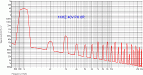
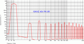
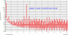
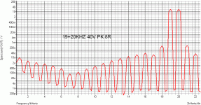
Simulation give quite good results notably very low THD and IMD
as well as high slew rate.
There s a few pictures below that must be of course taken with
a big grain of salt since it s only simulations albeit this will give
an accurate view of the general trend.
I d like to add a few observations for the sake of the technical discussion.
Providing an LR output filter is used stability seems good ,
in fact even without such a filter it is not easy to make it ring
other than marginaly using a relatively high capacitive load,
so it seems that the triple EF compensation work very well.
There s voluntarly high standing currents in the front end , something
that is advocated by R.Cordell for the VAS but in that case so much heat
is not needed since this stage is loaded by a triple EF that render useless
high drive currents.
The input differential current is high and all the thermal dissipation burden
is devoted to the common base pairs since the common emitter differential
has only 7.5V Vce , a value that will maximize its Cbc , 20V being necessary
to bring it close to its minimal value wich will also reduce the common base
stage TDP notably.
Enhanced VAS does not bring as much improvement as it would if a current
mirror was used in the source for obvious reasons but it help reduce THD by a few dB.
Cascoding the VAS would reduce LF THD to single digit ppm ratios but it
would lefts THD unchanged at 10khz or above while endangering stability
by a sizeable margin so it wont be missed , moreover with the already
very low distorsion ratios.
Anyway , a pleasant amplifier that is really high definition.
.
Attachments
Last edited:
The input differential current is high and all the thermal dissipation burden
is devoted to the common base pairs since the common emitter differential
has only 7.5V Vce , a value that will maximize its Cbc , 20V being necessary to bring it close to its minimal value
There is no Cbc minimum. Starting from 1 volt and up to the junction breakdown voltage, Cbc decreases with SQRT(Vbc). The only significant error in this sqrt law is around zero volts, where things are a little more complicated. With a very good approximation, at 20V each and every junction (BC, diode, etc...) will have a SQRT(20/7.5)~1.64 lower capacitance than at 7.5V. Classic Gray and Meyer textbook stuff.
Thanks for the analysis Wahab.
I kept the front end cascode voltage low in order to minimize dissipation - a point you guessed correctly but perhaps one that I should have highlighted in my text. Certainly, running at a higher cascode voltage would also reduce Cbc. However, since the collector voltage of the input pairs are fixed by the cascodes, Cbc impact is substantially reduced.
Of course the high front end current facilitates high slew rates, and because the LTP is resistively loaded, must also support the current through them as well as drive Cdom. As I note in my text, the othe option is MIC, which by doing away with Cdom, will support very high slew rates. This gies the option then of running the front end at lower LTP currents.
A number of people's commented on the Ovation 250 that the VAS standing current was very high - a point I concede. This design is much lower, but I still prefer to run it 'rich'. I guess this is where as a designer you have the latitude to do things a bit differently. In the simulations, I looked for minimum modulation of the VAS standing current and looked at output loads from 2 to 8 Ohms.
Output Inductor. Yes, the e-Amp comp is conservative with plenty of room even driving quite a heavy capacitive load. But, I always think about the worst case scenario of a 2uF electrostatic hanging off the output. Note also that in TMC comp mode, the phase and gain margin are lower.
There seem to be a lot of harmonics on your distortion plots
Last edited:
There is no Cbc minimum. Starting from 1 volt and up to the junction breakdown voltage, Cbc decreases with SQRT(Vbc). The only significant error in this sqrt law is around zero volts, where things are a little more complicated. With a very good approximation, at 20V each and every junction (BC, diode, etc...) will have a SQRT(20/7.5)~1.64 lower capacitance than at 7.5V. Classic Gray and Meyer textbook stuff.
The minimal value is at Vbc max of the device , isnt it ?...
Since this is a Sqrt law the reduction of Cbc over 10V start to become
marginal with increased Vbc , hence increasing Vcb to 20V , wich will
give a marginal improvement over 10V value but it was also to balance
TDP between the two parts of the cascode.
- Status
- This old topic is closed. If you want to reopen this topic, contact a moderator using the "Report Post" button.
- Home
- Amplifiers
- Solid State
- Ovation e-Amp is Completed
