I had some Nichicon KW 470uF 100V caps, but did not have enough for my second channel so I thought I would buy some Panasonic FC caps, I've not used them before.
The FCs finally came today, I'm surprised by how large they are compared to the KWs.
The FCs finally came today, I'm surprised by how large they are compared to the KWs.
Attachments
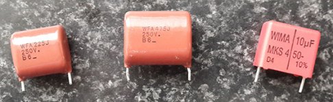
I still have not decided on Input caps.
I want to use some thing decent but I'm not sure what to use.
Here are some options, If there is any suggestion about other caps please post them.
I can only buy from RS Components at the moment, they charge me bout $7 for postage and there are no customs charges.
My previous order from mouser was $300, there was no postage charge but the customs in my country added $63 to that price, I did not expect them to charge that much.
Please any suggestions will be appreciated.
http://docs-europe.electrocomponents.com/webdocs/0f2e/0900766b80f2eacb.pdf
http://www.mouser.com/ds/2/440/WIMA_MKS_4-4147.pdf
Regards
Attachments
Last edited:
..... if you have money , they are expensive ,but good quality ....capacitor_film_auricap_xo.html
I still have not decided on Input caps.
I want to use some thing decent but I'm not sure what to use.
Here are some options, If there is any suggestion about other caps please post them.
I can only buy from RS Components at the moment, they charge me bout $7 for postage and there are no customs charges.
My previous order from mouser was $300, there was no postage charge but the customs in my country added $63 to that price, I did not expect them to charge that much.
Please any suggestions will be appreciated.
http://docs-europe.electrocomponents.com/webdocs/0f2e/0900766b80f2eacb.pdf
http://www.mouser.com/ds/2/440/WIMA_MKS_4-4147.pdf
Regards
I bought those Panasonic Polyprops few days ago. Finished building my amp last night and will see how it sounds tonight. I shall post findings regarding input cap.
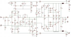
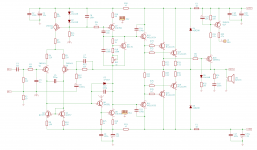
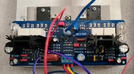
Just been wandering about transistor placement on heatsink.
Is it OK to place Vbe multiplier + Predrivers + Drivers + Output transistors all on main heatsink.
Or should Vbe multiplier + Output transistors all on main heatsink and
Predrivers + Drivers transistors bee on their own common heatsink ?
The PCB I made will allow for both options.
Thanks
Is it OK to place Vbe multiplier + Predrivers + Drivers + Output transistors all on main heatsink.
Or should Vbe multiplier + Output transistors all on main heatsink and
Predrivers + Drivers transistors bee on their own common heatsink ?
The PCB I made will allow for both options.
Thanks
Attachments
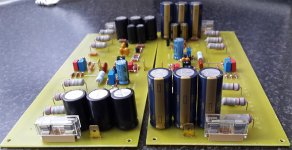
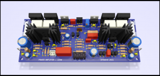
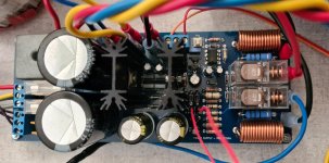
Ok so now all done, And everything working well.
Protection circuit all working too.
Now to mount all in a do it yourself enclosure.
Just another question about bias drift with thermal changes on main heat sink.
At some point the Iq bias though power transistors will change with a change in sink temperature.
How much change in bias is acceptable, let say from 24degC to 50degC.
Also whats your opinion, about either over bias, or under bias, i.e Iq decreasing/increasing with temp increase.
Regards
Attachments

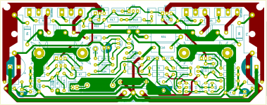
Here are some KICAD files for anyone that would like to look at this PCB software.
This is not a great layout, just something I used to see how this software works for myself.
regards
This is not a great layout, just something I used to see how this software works for myself.
regards
Attachments
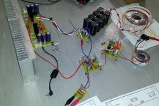
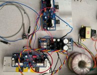
So i build this circuit with new power supply using ApexAudio NE555 design as a base, DC and short circuit protect work when tested independently.
Now to short the amp for real..... and see, output transistors are too expensive.
The amplifier modules sound real nice.
Now to short the amp for real..... and see, output transistors are too expensive.
The amplifier modules sound real nice.
Attachments
Last edited:
- Status
- This old topic is closed. If you want to reopen this topic, contact a moderator using the "Report Post" button.
- Home
- Amplifiers
- Solid State
- Second attempt at Building my own amp from scratch