This is the progress of circuit 2.
Ive learned much, adding to circuit one thing at a time,
still so much to learn")
I need advice please,
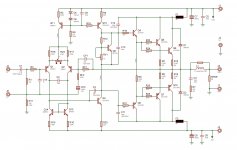
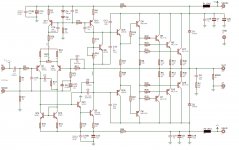
Q12,3,21 Any advice on which transistors to use here,
The ones shown are Vce=120V and wont do.
Ill still make some changes and tweak some values.
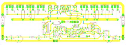
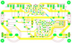
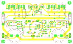
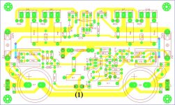
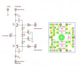
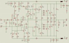
Here is circuit and pcb, pcb needs more work.
Regards
Ive learned much, adding to circuit one thing at a time,
still so much to learn
I need advice please,
Q12,3,21 Any advice on which transistors to use here,
The ones shown are Vce=120V and wont do.
Ill still make some changes and tweak some values.
Here is circuit and pcb, pcb needs more work.
Regards
Attachments
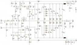
Remove RV2. Remove 3pr of output devices. Reduce the supply voltage to about +-35Vdc.
Don't fit CF1, nor C2, nor C16. Leave the pads in the PCB in case you need them for compensation.
Now you have a much simpler circuit and PCB to work with and more likely to understand what you measure on the working amplifier.
With the lower rail voltage, you don't need any high voltage transistors and that makes sourcing all your transistors easier.
Last edited:
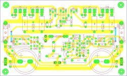
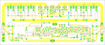
Havent had much time but I just want to ask if this is a better layout,
Im also asking for advice on what I'm doing wrong on the pcb layout.
Ive built up the old pcb and it works reasonably well, just a small bzzz sound when you place your ear closer than 50cm to tweeter.
Pot body is metal and grounded.
Also have main ground to earth.
I have a pot on input, the bzz does not get any louder, when pot is at min or max, with input floating.
At max volume it delivers the full 100W, and plays Bass to High nicely.
Thanks
Attachments
@Vostro, your decoupling caps at the supply line don't need to be a 1000uf per rail..most amps use say 100uf to 220uf's.. followed via 220nf's.
An idea would be to add a speaker protection relay to soft start and this will stop the on/off thumps plus the circuit will cut off amp from speaker in case large dc is found on the o/p..
Just one question, what is your ac voltage reading on the o/p before clipping kick's in??
An idea would be to add a speaker protection relay to soft start and this will stop the on/off thumps plus the circuit will cut off amp from speaker in case large dc is found on the o/p..
Just one question, what is your ac voltage reading on the o/p before clipping kick's in??
Thanks for reply, the two caps are 10000uf and is intended as main smoothing,
Just bridge and transformer off board.
My board is sadly lacking in decoupling.
In initial testing with the first board from previous post,
I was running from a 30V-0-30V 300VA transformer,
When running a 1kHz sinewave into 8R resistive load the amp started clipping
at about 77Vp-p out, 27.2Vrms giving 93Wrms into 8R.
Im now running it from a 35V-0-35V 500VA transformer, aloowing amp to deliver
over the 100W in original design goal.
I have some transformers not in use, so I just used them here to test.
Regards
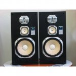
I have one Sansui S-900G (sample pic added) here that I use to test amplifiers with.
Its the remains of a component Sansui system that blew up and took out its speakers with it, all three speakers in the one box was destroyed, along with the tweeter and mid in the other one, just leaving the 10in bass. The owner decided its to costly to repair and replace, so he left the speaker with me.
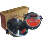
I used two Audiopipe ATX-3720(mine with MKT caps not electrolytics as in sample pic) to replace the blown mid and tweeter with, producing nice speaker box that I don't mind to thump.
I connected this amp to this speaker today and Im surrpised with the sound,
its not bad at all, driving the 10in bass to the max and still giving a
clear and crisp signal to the tweeters.
Im going to build up this circuit which is similar just with upgrades, (edit: Im also changing VAS to darlignton)
so hopefully by next weekend I'll see if I can hear the difference between the two.
Regards
Its the remains of a component Sansui system that blew up and took out its speakers with it, all three speakers in the one box was destroyed, along with the tweeter and mid in the other one, just leaving the 10in bass. The owner decided its to costly to repair and replace, so he left the speaker with me.
I used two Audiopipe ATX-3720(mine with MKT caps not electrolytics as in sample pic) to replace the blown mid and tweeter with, producing nice speaker box that I don't mind to thump.
I connected this amp to this speaker today and Im surrpised with the sound,
its not bad at all, driving the 10in bass to the max and still giving a
clear and crisp signal to the tweeters.
Im going to build up this circuit which is similar just with upgrades, (edit: Im also changing VAS to darlignton)
so hopefully by next weekend I'll see if I can hear the difference between the two.
Regards
Attachments
Last edited:
Also power out in to 8 ohms is 93w and into 4 ohms comes out at 27.2 divided by 4 ohm gives 6.8 amps times by 27.2 = 184.96 watts. nice circuit.. just add v-limiter circuit in there and this will steal the drive voltage away from the o/ps in case of short circuit to the o/p.
if linked in bridge mode your have roughly 370w @8 ohms.
if linked in bridge mode your have roughly 370w @8 ohms.
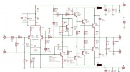
After final checks I made some changes, Ill build when I get the chance.
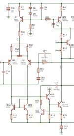
I have some more questions on other design,
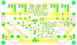
(#1) I would like to know where I should ground these two points on PCB,
The simulation with the "darlington VAS" caused Q3 to saturate badly,
so I added Q22, in simulation it seemed to work.
(#2) Id like to know If I added Q22 corectly, not totally sure about R17.
Thanks
I have some more questions on other design,
(#1) I would like to know where I should ground these two points on PCB,
The simulation with the "darlington VAS" caused Q3 to saturate badly,
so I added Q22, in simulation it seemed to work.
(#2) Id like to know If I added Q22 corectly, not totally sure about R17.
Thanks
Attachments
Late Edit:
only when amplifier is diven into clipping the output.The simulation with the "darlington VAS" caused Q3 to saturate badly
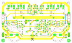
I think I'm done and ready to build if I get some free time,
I decided to use 3 pair output since it fits my heatsink
Ive not decided on which driver transistors to use yet.
Im using MJ21194/3 OPS since I have some.
I was wondering it it will hold up to 4ohm load (2 amps bridged)
from 35V-0-35V 500VA toroid.
It will go into BassBin with single 400W 12inch 8R Bass speaker.
Making a active Bass speaker for a friend of mines bass guitar.
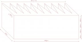
Also if I use the heatsink in attach, what length heatsink would be good
per amplifier.
Also is V/I limiter only way of protecting against short speaker terminals,
I think I must include this .
And lastly What is max supply votage you would reccomend for 4R and 8R speakers.
Thanks so much,
I decided to use 3 pair output since it fits my heatsink
Ive not decided on which driver transistors to use yet.
Im using MJ21194/3 OPS since I have some.
I was wondering it it will hold up to 4ohm load (2 amps bridged)
from 35V-0-35V 500VA toroid.
It will go into BassBin with single 400W 12inch 8R Bass speaker.
Making a active Bass speaker for a friend of mines bass guitar.
Also if I use the heatsink in attach, what length heatsink would be good
per amplifier.
Also is V/I limiter only way of protecting against short speaker terminals,
I think I must include this .
And lastly What is max supply votage you would reccomend for 4R and 8R speakers.
Thanks so much,
Attachments
Vostro, v/I limiter or multi slope is a standard way in many amplifier circuits as with out them more damage can and will happen if o/p stage takes a direct dead short.. the main point of these simple circuits is to remove the drive voltages to the o/p devices.. take a look in to amplifier 'cook' books such as G randy slone's high amp book he out lines such circuits.
your question regarding using your amp in four ohms bridged.. try it at 8 before pushing it down to 4 ohms...(some power amps use more o/p devices to aid current share at such low loads.
max supply rails for your amp could run up to 60 vdc/ 70vdc.. but a safe bet would be 50vdc. your get more power output at different dc rails and up grade your filter caps to say 10000uf to 20000uf at higher dc rated..
anyway put things together and let us see...
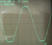
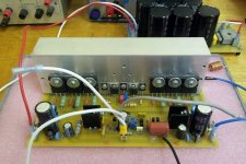
Ive Built up my next Amp, Running from 45V-0-45V AC, using 3x MJL21194/3 as outputs.
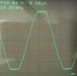
To test it, I played a 20Hz, 1kHz, 20kHz signal into 8R resistive load.
Clipping starts at 180W into 8R, if I change RC filter for IPS rails I guess I could get more, but Im fine with 180W into 8R.
But I have a question about the clipping behaviour
The trailing slope of the positive halfcycle at output is clipping weird.
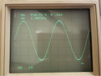
At 1khz its noticeable and at 20khz its very visible.
Im not sure what causes this, Advice will really be appreciated.
Thanks,
Vostro
- The Miller Cap is 100pf, ive not lowered it to 47pf yet,
- The amp is connected as is, no added protection baords etc.
- Aprox currents are indicated.
- Heatsink is only for testing.
To test it, I played a 20Hz, 1kHz, 20kHz signal into 8R resistive load.
Clipping starts at 180W into 8R, if I change RC filter for IPS rails I guess I could get more, but Im fine with 180W into 8R.
But I have a question about the clipping behaviour
The trailing slope of the positive halfcycle at output is clipping weird.
At 1khz its noticeable and at 20khz its very visible.
Im not sure what causes this, Advice will really be appreciated.
Thanks,
Vostro
- The Miller Cap is 100pf, ive not lowered it to 47pf yet,
- The amp is connected as is, no added protection baords etc.
- Aprox currents are indicated.
- Heatsink is only for testing.
Attachments
- Status
- This old topic is closed. If you want to reopen this topic, contact a moderator using the "Report Post" button.
- Home
- Amplifiers
- Solid State
- Second attempt at Building my own amp from scratch