It is a discrete amplifier to be released end of July 2012.
To be used as an auxiliary amplifier, able to put out from 1 to 20 watts RMS, depending the supply voltage and the output impedance.
To be feeded, as power supply, from 9 plus 9 volts (batteries in series) to 16 plus 16 volts supplies (transformer, rectifier and filters)
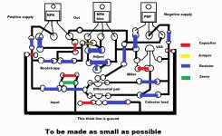
A simetrical supply is used, darlington transistors in the output, total of 6 transistors only...the smallest board as possible.
To be installed inside speakers, or small cabinets (enclosure)
To be an amplifier to PC, notebook, netbook, tablets, Ipod, Ipad, Cell Phone, Iphone, MP3 player, MP4 player, Tape recorders or any need of auxiliary power amplification.
Circuit is traditional, alike Dx amplifier (standard), to be tiny and to distort not more than 0.1% RMS (THD).
More details in this video:
Dx disintegrated circuit - Dx Dc - YouTube
Circuit will be provided after further testing (real world test).
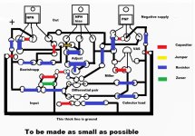
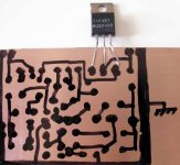
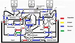
A kind of board suggestion is shown in the image below.
regards,
Carlos
To be used as an auxiliary amplifier, able to put out from 1 to 20 watts RMS, depending the supply voltage and the output impedance.
To be feeded, as power supply, from 9 plus 9 volts (batteries in series) to 16 plus 16 volts supplies (transformer, rectifier and filters)
A simetrical supply is used, darlington transistors in the output, total of 6 transistors only...the smallest board as possible.
To be installed inside speakers, or small cabinets (enclosure)
To be an amplifier to PC, notebook, netbook, tablets, Ipod, Ipad, Cell Phone, Iphone, MP3 player, MP4 player, Tape recorders or any need of auxiliary power amplification.
Circuit is traditional, alike Dx amplifier (standard), to be tiny and to distort not more than 0.1% RMS (THD).
More details in this video:
Dx disintegrated circuit - Dx Dc - YouTube
Circuit will be provided after further testing (real world test).
A kind of board suggestion is shown in the image below.
regards,
Carlos
Attachments
Ahahahahah! .... SMD produces and result in a bad amplifier?
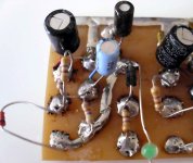
Well....i do think i was the one that made SMD by the first time in 1960....i was 9 years old...soldering at the copper side.... without holes in the circuit board.... it is good, maybe better as coupling is less.... less size, less body, less electromagnetic waves transmitted to nearby circuits.")
I have not registered..but no one made this way before me...or at least i could not see in European and US magazines such kind of construction.... surface construction the way i use to make.
Maybe you do not know uncle Charlie my friend from Australia (Qusp)..... this is the kind of construction i love to make in my prototypes
I cannot Meanman... i just cannot....i cannot see, even wearing glasses.... and this is DIY, something to everybody build..old bugger alike me and young eagle eyes too.
regards,
Carlos
Well....i do think i was the one that made SMD by the first time in 1960....i was 9 years old...soldering at the copper side.... without holes in the circuit board.... it is good, maybe better as coupling is less.... less size, less body, less electromagnetic waves transmitted to nearby circuits.
I have not registered..but no one made this way before me...or at least i could not see in European and US magazines such kind of construction.... surface construction the way i use to make.
Maybe you do not know uncle Charlie my friend from Australia (Qusp)..... this is the kind of construction i love to make in my prototypes
I cannot Meanman... i just cannot....i cannot see, even wearing glasses.... and this is DIY, something to everybody build..old bugger alike me and young eagle eyes too.
regards,
Carlos
Attachments
Last edited:

Oh! .... i forgot the emitter resistors! ... thank you.
I will install them.
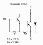
But, by the way, the Dx amplifier have not used the power emitter resistors not to kill bass.... hundreds have assembled and no one have complained about bias stability...it uses a darlington too...an emitter follower that is almost a darlington...watch what you have inside this darlington, for instance.... see that is connected as a emitter follower (modified)
Not all that different.... gain is almost the same as the Dx amplifier output.
regards,
Carlos
I will install them.
But, by the way, the Dx amplifier have not used the power emitter resistors not to kill bass.... hundreds have assembled and no one have complained about bias stability...it uses a darlington too...an emitter follower that is almost a darlington...watch what you have inside this darlington, for instance.... see that is connected as a emitter follower (modified)
Not all that different.... gain is almost the same as the Dx amplifier output.
regards,
Carlos
Attachments
Last edited:
just in case you missed the sarcasm, that was sarcasm. I dont wear glasses full stop, the vast majority of builds I do are SMD, I much prefer to build smd and I actually think to build truly hi performance amp with parts made this century its unavoidable. I was just commenting on what appears to be popular opinion here and all over the web in audio circles, its quite funny. sometimes people will remove a high quality SMD part to replace with a part that is basically the same, but PTH, thus actually performs much worse.
Hi
I think that there is something else going on if adding small emitter resistors to the output transistors affects the sound. The effect of the emitter resistors is that they reduce the %difference in output resistance of the output transistor (intrinsic resistance) between large and small signal conduction. Analog electronics design is all about comprimise.
Remember that temperature co-efficient of the driver is multiplied not summed by the co-effecient of the output device. This means having them in the same package and thus the same temperature has a larger effect on overall temperature stability than using seperate descrete components for driver and output, hence the need for a Darlington Vbe multiplier. The overall effect of the emitter resistors on thermal stability will be larger as well.
Hi Carlos
Have you ever experimented with the amplified diode model as described by Dr Hawksford in this paper? It is particularly designed to counter the effects of the large variance in current gain vs Ic for Darlington power transistors. The beauty is that this concept (illustrated in Fig 5), besides loading the VAS with a higher, more constant Z and nullifying the reflection of the load to the VAS, it can be easily reconfigured to work with vertical mosfets.
Have you ever experimented with the amplified diode model as described by Dr Hawksford in this paper? It is particularly designed to counter the effects of the large variance in current gain vs Ic for Darlington power transistors. The beauty is that this concept (illustrated in Fig 5), besides loading the VAS with a higher, more constant Z and nullifying the reflection of the load to the VAS, it can be easily reconfigured to work with vertical mosfets.
I could realise that people are not watching the video explaining the project
.... i concluded that because video's hit counter is smaller than this forum's hit counter...and there are other foruns too that should increase video's hits....so, people does not know that there's a video explaing some more details.
Here you have the video, many others will be made, because audio and video is 100 times more efficient that text and pictures.... being an extra help for us to communicatte:
Dx disintegrated circuit - Dx Dc - YouTube
I do think future foruns will have videos attached on screen and chat room with audio communication alike Skype or something like that...this is a need for modern communication.
Please, take a look at the video and criticise if you think it is too long or that repeat things in order for me to have a feedback and to evolute the stuff.
The first forum that include these features will steal thousands and thousands of subscribers from ancient foruns.
There are comment line below the video, and you are free to criticise in order to help me to make it better..... i do imagine it is big...too much big, but this is to be confirmed.
regards,
Carlos
Last edited:
it is always very nice to see uncle Charly to be productive ....
here is a couple of things
Darlingtons are notorious for stability issues when it comes to audio amps ... from repair experience i can tell you that all of them will fail in some time ....Your case since rails are too low you might get away with it .
one other problem is that normally your amplifiers are smashing hits ...when the circuit is ready loads of people will go for construction then the problem will be the choice of darlingtons per user per country ... not all of them available in all countries .
Then the total and final problem is that depending first in the question fake or not but also regarding model /make/brand and batch we don't know exactly the configuration of the darlington inside ..... a BDV 66 made from Thomson has different configuration inside than a BDV 66 from Philips and both of them have different specs depending on the batch and the specific order .
that will result to bad feedback and eventually stability issues not god for the DX corporation ( even though you still might get away with it since rails are very low )
i will vote for no darlingtons
Your friend
sakis
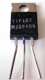
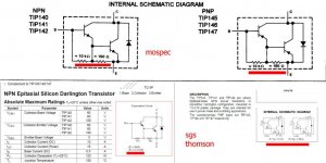
here is an example of the well known TIP 142 -147 family and the specs of 3 also well known manufacturers where you will notice that the configuration inside is different even though here we talk about respectable manufacturers ....imagine how things are going to be in the secondary production or the fake industry....
manufacturers are MOSPEC SGS Thomson and fairchild
manufacturers are MOSPEC SGS Thomson and fairchild
Attachments
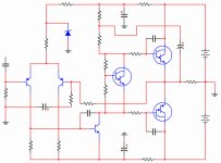
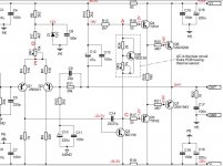
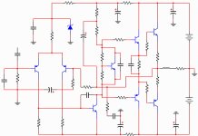
Here is the schematic...old Dx amplifier style
Distortion dropped from 0.9 to 0.047 %
My intention is to make it smaller.... a discrete IC.... this will be a trouble using transistors.
First i gonna check with darlingtons, some torture to see how they gonna behave and then i may go to the bigger one.
The idea is to make it simple and small.... stability issues will be checked real world.... i have made some darlington stable amplifiers...i know some tricks to make the stuff stable..gonna apply them.
The bigger one, this one posted, is a return to the Dx amplifier...there's no point to return...the idea is to make it simple folks...there's some stop resistors that we can remove, some parts that can be removed, that may impair the distortion a little bit but can make it smaller...it must be smaller or gonna die.
regards,
Carlos
Attachments
Last edited:
- Status
- This old topic is closed. If you want to reopen this topic, contact a moderator using the "Report Post" button.
- Home
- Amplifiers
- Solid State
- Dx Disintegrated Circuit - Dx Dc