I'd think a balanced input will always reject more common mode noise/hum than unbalanced. That said, I've never seen a problem with standard single ended pre and amp connections. It may not be a universal law like gravity, but I also think there's an inherent internal noise penalty with a differential input because you've got another channel of active devices. The only way around that would be the use of a transformer, which should have near zero noise contribution. So, if you need differential, use it, otherwise single ended will most likely beat it for self generated noise and THD.
Thank you for your response. I understand and agree with you in general. My question was about this specific design, as I've read about some circuits that lower the noise by only 20 dB and others that can do much better.
I've also read about transformers being the best way to ´unbalance´ a signal, but this is a supposedly good amplifier (Cambridge 840W) and was wondering if the balanced input was also well designed, on the opinion of the knowledgeable people around here.
Thanks again.
I've also read about transformers being the best way to ´unbalance´ a signal, but this is a supposedly good amplifier (Cambridge 840W) and was wondering if the balanced input was also well designed, on the opinion of the knowledgeable people around here.
Thanks again.
Beranga,
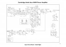
The Cambridge Azur 840W power amplifier has balanced line level, signal splitting transformers on its inputs to allow its use in numerous ways beyond most other audiophile brands and models, moreover like that found on pro AV gear (signal looping, for one example), although with much lower distortion. The matching Cambridge preamp utilizes balanced line level output transformers. This combination allows simple worry-less connectivity without the chance of stray AC or DC offset being introduced into the signal chain.
Sorry to say, the preamp schematic you posted is of far less signal caliber than the Cambridge amplifier. The 840W amplifier is probably best matched - connected to the 840E preamplifier. The engineers seriously designed these units to work very well together especially via their balanced connections.
Best Regards,
Rich
Would you say the balanced input of this amplifier has better noise rejection or any advantage over its RCA input? I understand the amp is not fully balanced, but my preamp is, so what do you think?
Thanks in advance.
No.
The shield is connected to signal earth and therefore all external interference/noise is directly injected into the audio path.
What you want is a separate path for the interference/noise as is described in the AES48 standard. Iaw shield to the chassis!
aes48-2005-f
Beranga,
I should have said that I realize that the preamp schematic is by Cambridge. It's design capability is simply not on par with the latest 840E preamplifier and 840W power amplifier.
These units work very well together especially via their balanced connections.
Best Regards,
Rich
I should have said that I realize that the preamp schematic is by Cambridge. It's design capability is simply not on par with the latest 840E preamplifier and 840W power amplifier.
These units work very well together especially via their balanced connections.
Best Regards,
Rich
No.
The shield is connected to signal earth and therefore all external interference/noise is directly injected into the audio path.
What you want is a separate path for the interference/noise as is described in the AES48 standard. Iaw shield to the chassis!
aes48-2005-f
Thank you Dirk, I will have a look at that paper.
Beranga,
I should have said that I realize that the preamp schematic is by Cambridge. It's design capability is simply not on par with the latest 840E preamplifier and 840W power amplifier.
These units work very well together especially via their balanced connections.
Best Regards,
Rich
Rich:
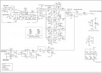
Thank you for your response. Actually, what I posted is the schematic for a 840W amplifier, straight out the service manual. I posted it without the title to make the file smaller, but here it is complete:
Attachments
Last edited:
I would first ask why pins 8 and 2 were left floating
rather than 52K returns from the output? Has some
mission critical information about this "terrapin" been
left out?
Kenpeter, thanks for your input, but at what pins are you referring?
Edit: Never mind, I found the pins you talked about. Thanks
Last edited:
You'll find a discussion of this circuit in Douglas Self's Small Signal Audio Design book - he designed it, the whole 840W in fact. Essentially the point was not only matching, but even exceeding unbalanced input noise specs since people usually (if mistakenly) expect balanced inputs to perform better. The mysterious "terrapin module" must have pretty good current drive capabilities.
You'll find a discussion of this circuit in Douglas Self's Small Signal Audio Design book - he designed it, the whole 840W in fact. Essentially the point was not only matching, but even exceeding unbalanced input noise specs since people usually (if mistakenly) expect balanced inputs to perform better. The mysterious "terrapin module" must have pretty good current drive capabilities.
Excellent advise!!! That book contains everything I wanted to know about the amplifier. Thank you.
My sincerest apology to all readers. I completely spoke out of turn, my comments based entirely upon misinformation instead of first hand knowledge regarding the Cambridge W840 power amplifier and E840 preamp.
Very truly,
Rich
No need to apologize, just clearing things up
")
Thank you Dirk, I will have a look at that paper.
I have to clarify some things.
If the shield of the interconnect cable is connected to the signal earth you inject all interference into the audio path. So in that situation there is no benefit in going balanced. Unfortunately this is the case in 99% of all situations. So the first step of improvement in noise rejection is connecting the shield directly to the chassis so there is a separate path for the interference to go. This interference will always be there because of the voltage differences between the connected devices.
Second step in reducing interference is making sure the impedances of the positive and negative audio cables are the same across the audio frequency band. Best way to do this is using trannies. But you can also bootstrapp the input so differences in impedance are not important any more, the That 1200 series is developed for this purpose.
For a device to be AES48 compatible (What means that the device is immune to outside interference), you do not need it to be fully balanced. Just the input and output need to be balanced. The PDF has some good drawings that shows how a device should be wired.
But why anyone other than professional recording businesses or telephone companies would want balanced connections is a mystery to me.
Hi Dirk,
I agree with you that it is good practice to connect the shields of balanced audio cables according to the AES48 standard, but I think you are exaggerating a bit when you say that balanced connections are useless when you connect the ground to the internal signal ground. Sure, stray currents through the internal signal ground will cause interfering voltages that the circuit can't reject when it is internally single-ended, but at least you are still insensitive to the voltages across the shields of the cables.
Balanced connections are useful when you have large ground loops, like when you have three studios that are all connected to each other, or when you have a home audio set that is grounded to the mains safety ground and to the cable RTV ground. In this latter case you can usually just as well break the ground loop by blocking capacitors or a tiny transformer in the cable connection.
Best regards,
Marcel
No.
The shield is connected to signal earth and therefore all external interference/noise is directly injected into the audio path.
What you want is a separate path for the interference/noise as is described in the AES48 standard. Iaw shield to the chassis!
aes48-2005-f
Dirk:
Sorry for the newbie question, but why do you say the shield is connected to signal earth? What I see in the diagram is pin number one of the balanced input connected to chassis ground.
Your correct, I misread the schematic and made the wrong assumption that 99% of all equipment is not AES48 compatible.Dirk:
Sorry for the newbie question, but why do you say the shield is connected to signal earth? What I see in the diagram is pin number one of the balanced input connected to chassis ground.
But then you have to make sure all the rest of your equipment is also AES48 compatible or else a very loud noise will be heard.
Your correct, I misread the schematic and made the wrong assumption that 99% of all equipment is not AES48 compatible.
But then you have to make sure all the rest of your equipment is also AES48 compatible or else a very loud noise will be heard.
Very interesting read, the AES paper. Thanks again.
Very interesting read, the AES paper. Thanks again.
The shield to chassis earth is key to reducing noise.
Then you must make sure CMRR is low to. This is not so eazy to do and puts great demands on interconnect dimensions and tolerances. Here you can find info on how to get the best CMRR: http://www.jensen-transformers.com/an/ingenaes.pdf
- Status
- This old topic is closed. If you want to reopen this topic, contact a moderator using the "Report Post" button.
- Home
- Amplifiers
- Solid State
- Balanced to unbalanced schematic, is this one good?