Hi fellows, I want to build my first amp and think a 50W Class AB all in BJT would suit fine (less heat and power consumption). I'm looking for a good quality project rather than a cheap one.
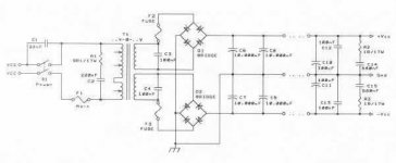
I already have an idea for the psu part (see image)
Any suggestions about the circuit?
Any link I can go take a look at?
Thnx ya'll
morBin
I already have an idea for the psu part (see image)
Any suggestions about the circuit?
Any link I can go take a look at?
Thnx ya'll
morBin
Attachments
Morbin,
The Aksa 55 watt kitset amplifier is a truly marvelous product.
http://www.printedelectronics.com/products/products.html
All bipolar and runs cool as a cucumber.....
The Aksa 55 watt kitset amplifier is a truly marvelous product.
http://www.printedelectronics.com/products/products.html
All bipolar and runs cool as a cucumber.....
Newbie Amp
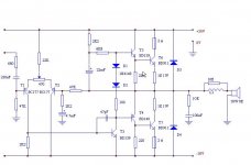
I Built this amp about milion times...it is not the best sounding amplifier....but it works realy fine... It is base schematic, it has some obsolete components tha can be raplacet with some newer... It also can be upgraded in many ways but i will leave that to you") I also have PCBoards and all the rest...
I also have PCBoards and all the rest...
I Built this amp about milion times...it is not the best sounding amplifier....but it works realy fine... It is base schematic, it has some obsolete components tha can be raplacet with some newer... It also can be upgraded in many ways but i will leave that to you
I also have PCBoards and all the rest...Attachments
being someone who started on citation 12, I would suggest that you do one of those: it is very much like P3A but without an emitter follower stage. the schematics is pretty easy to find.
I have been testing a mosfet version of it for some time now, only in simulation tho. since you had asked for an all bjt design, I replaced the mosfets with mje15030/1 and ran it through my simulator. It worked quite well: 0.017% thd at 20khz full power into 8ohm, and 0.011% thd at 1khz. for 4ohm, it delivers 0.067% at 20khz and 1khz.
I will post the schematics later if you want.
Re: Newbie Amp
it is quite simple but may need some tweaking:
1) one can do with a full complementry OPS now.
2) I would float the 220 resistor on the emittor of T5;
3) one may want to change the 2k2 resistor on T1's collector so that the current going through T1 and T2 is roughtly the same. a 1K resistor will do that.
I thought using diodes for biasing purposes is quite simple but I haven't tried it in any real amp. Has anyone done that?
Drafance007 said:I Built this amp about milion times...
it is quite simple but may need some tweaking:
1) one can do with a full complementry OPS now.
2) I would float the 220 resistor on the emittor of T5;
3) one may want to change the 2k2 resistor on T1's collector so that the current going through T1 and T2 is roughtly the same. a 1K resistor will do that.
I thought using diodes for biasing purposes is quite simple but I haven't tried it in any real amp. Has anyone done that?
Hey Millwood I appreciate that!
Post the schematics please.
The THD looks good to me, but to be sure on how it sounds, one should build it and listen to it, right?
This is my first amp, but I want to last it a long while!! (quality listenings I mean)
I'm quite new into amp diy, but I'd like to know as much stuff as I can before deciding for my best pal.
morBin
Newie Project
There is no reason why this amp. It is very regular conception amplifier... Citation 12 is superior than this amp. Also many other. It is your choice. I was given this schematic a long time ago when i wanted to build simple but functional amplifier, so i guess maybe you would be intrested.
I didn't realy ever measure power of this amp, but i think that it can give about 50-60w rms on 4 ohm load with less than 1% thd.
The modifications that were sugested by -millwood- would be fine for this amp. There are also some other but the amp would be much complicated after.
You can build this thing with anything that you have in house...it will still work. I tryed for output transistors many stuff, even 2n3055, BD249, BD243C... It is realy cheap... Power supply may cost you samo money and cooling...all the rest is cheap.
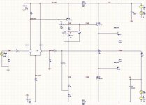
here is it. It still has too many net lables on it.
a few things:
1) the two sin voltage sources are there since I wanted to see how the amp reacts to fluctuations in PS.
2) R20/21, C20/21 are there to decouple the input and VAS from PS ripples. You don't have to have them.
3) Q6/7/8 should be a little beefier transistors even tho. they are working within their spec.
4) the gain peaks to about 30x at 2mhz. Parralleling a 1pf cap across R6 cures it: it now peaks to 22.5x.
5) thd, under a less than perfect PS (with a 5v 50hz ripple), is 0.013% at 20khz into 8ohms.
the amp is inspired by citation 12 and in part by p3a. the input and VAS use identical topology, with the OPS being fully complementory now. so it should work.
However, I have not built it. so I cannot tell you how good / bad it sounds or tell you definitively that it works. I am working on a mosfet version of it, tho.
Please comment.
Attachments
morBin said:what makes you choose Mosfets instead of BJT?
nothing in particular other than that I have a bunch of 540/9540 that I got from like 15 years ago and I have had good results with those devices in a citation 12 (from that era too).
they are very sturdy, hard to destroy (with a simple v-i limiter), and they are very cheap.
You do however have to deal with their propensity to parasitic oscillation, gate capacitance (no long leads for example) and low efficiency.
I have never used newer mosfets (like the irfp variants), and would love to see how they work in audio.
Hi morBin,
My first and second amps were the AKSA 55 and Rod Elliott's P3A. Both are excellent amps.
IMHO, the AKSA is slightly easier to build because all the amp components are supplied with the kit and the PCB has large pads and solder masks making soldering fairly easy.
If you get the AKSA, think about getting the Nirvana upgrade kit at the same time. This will save you a bit of work in the long run.
I'm thinking about using the same power supply as the original poster... but I haven't been able to puzzle out the value and voltage of the resistor on the AC side of the transformer (with the 220nf capacitor). Any suggestions?
Also, if I will be using 45v transformer secondaries, do I need a beefier voltage rating for the two 1R/17V resistors (R2&R3) on the tail end of the supply?
Thanks!
Also, if I will be using 45v transformer secondaries, do I need a beefier voltage rating for the two 1R/17V resistors (R2&R3) on the tail end of the supply?
Thanks!
- Status
- This old topic is closed. If you want to reopen this topic, contact a moderator using the "Report Post" button.
- Home
- Amplifiers
- Solid State
- 50W Class AB BJT suggestions for newbie