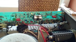
Well, I finally got around to upgrading the caps and am having some issues. I am popping the rail fuses. One on each side. On the left channel, I am popping the positive rail fuse as circled in red in the picture. On the right channel, I am blowing the negative rail fuse. Both fuses blew after powering it on with heatsinks bolted in place. When I first powered it on the left channel positive fuse blew but I did not have a fuse in the right channel negative slot. I had taken it out and forgot to put it back in. So when I first powered it up I had both fuses in place on left channel and only the positive rail fuse on the right side so I thought I only had an issue with the left channel. Then I noticed that the negative rail fuse was not installed on the right channel. Before powering it on again, I checked around to see if I had a short on the right heatsink. I couldn't measure one, so I put a fuse in and it popped as soon as I flipped the power switch.
As you can see in the pics, I took the heatsink back off the left side. Putting both fuses in and powering the amp on nothing blows. So it would seem that there is a short caused by mounting the heatsink. I know that the transistors need to have the insulator installed and it was in place when the fuses blew. I have checked the areas where I soldered and I can not see any solder bridges. I only soldered 8 spots ( 4 caps). They are circled in white. Cap C7 is the large 220uf non polar electrolytic which was swapped with the 220uf Bi-polar Muse which is a direct replacement. Cap C6 was replaced with a .47uf Wima MKP4. This is the bypass cap for C7. I installed it with writing facing up, same as the Wima MKS4 which was there previously. C1 was removed all together and C2 was replaced with a 4.7uf Claritycap ESA MKP film cap upon recommendations from AndrewT and others in my other thread. I actually installed this in the location of C1 as the mounting tabs on the board were larger and easier to open up a bit for the larger lead diameter of the clarity cap. Since these were in parallel to begin with, I don't see that as being an issue. The only other cap I swapped was C12, a .1uf MKS4 which I swapped for a .1uf mkp4.
Now, this amp was working fine before changing caps. Like I mentioned above, the left channel stopped blowing the fuse when i removed the heatsink. It only blew the positive fuse (red lead). I have not yet reinstalled the heatsink to see if the problem reoccurs. I did check the center leads on the transistors on the other channel and got no continuity to ground with one lead grounded to the chassis. I thought this side should be good but as soon as I put a fuse in the empty slot. it popped that one as well. (negative/blue lead).
Not sure what is going on. I immediately suspected a short to chassis through the transistor but this does not seem to be the case. I have now pulled the right channel heatsink and this side is now ok as well. All fuses are in and the amp powers up and the fuses hold. This points to a short with the Heatsink but I can not find one. I also checked my solder points on this side and no issues. I am using Artic silver 5 for thermal paste and the insulators that were originally installed.
anybody have any suggestions as to what might be going on or what to test? i don't see an inherent issue with the replacement parts as being the issue and everything works with heatsinks off, but as mentioned, don't see a short either. really stumped.
Mike
Attachments
How many threads have this same enquiry?
Enquiry about fuses popping in general or about Artic silver causing the problem? Obviously knowing of something that is a potential issue makes searching for it easier. Seeing as Artic Silver is said to be nonconductive, I would not have suspected it. If this is not what you suspect, could you point me in the right direction of what to search for please. You were very helpful in my original thread, and I spec'd my parts based on your recommendations.
you know, I kept trying to understand how something that is supposed to be 99% silver can not be conductive, but before I used it, I searched google and everything came back nonconductive. I did not search this site. If I hadn't already been misled to believe it to be ok, I wouldn't been so perplexed. So pretty much the paste is the whole issue. It's the only thing that makes sense based on what I am seeing.
Mike
Mike
Hello Mike,
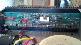
Casting a quick eye over the photo you posted, can you clarify whether the Red Block WIMA cap at the extreme left near the amplifier output leads, is original or has been a modification at some stage.
The board seems to be a mirror image enabling correct orientation for left and right channels inside the chassis. Looking to the equivalent overlay on the pcb on the right I note the spaces provided for C15 and R34 differ from what I see at the left.
The resolution in my laptop is not good enough for me to spot if there is a resistor sitting below the Red Block WIMA cap on the board as mentioned above. This resistor would have to be around 5 watts or so in rating and it might have been more easily seen in the photo.
This combination of capacitor and resistor forms a stability network and if the resistor is missing or replaced by a component of smaller rating there could be stability issues that are the cause of blowing fuses.
It is a good idea when trouble shooting power amps to disable the channel that is not in focus. Blowing fuses is also inconvenient so a couple of 7 watt 1k wirewound resistors in parallel - you can twist the leads at either end and solder each end so formed to a small alligator clip and use these to bridge across your fuse holders. You can measure the voltage drop across the fuse holders with these in place to work out roughly the amount of current being drawn due to a fault condition.
Another sign of fault is heating of these bridge resistors - a moistened finger is a quick test I have used before using a meter. Keep the your free hand on the on/off button switch if these become too hot to touch.
Michael Jonassen
Last edited:
Arctic Silver 5
Actually, the sales talk is that only the silver part is 99%, like saying this amp. case is 100% steel etc. I note they
warned you might measure capacitance between pins if you contaminated connectors with the stuff.....Hmmm
I would guess you got 99% of 5% there or they would be asking a lot more than $5 for a few grams.
Hello Mike,
Casting a quick eye over the photo you posted, can you clarify whether the Red Block WIMA cap at the extreme left near the amplifier output leads, has been replaced at some stage. The board seems to be a mirror image enabling correct orientation for left and right channels inside the chassis. The spaces provided for C15 and R34 differ from what I see at the left.
I believe they are the original caps. WIMA mkp10. I'll check values when I get home. It is position C15. According to schematic, should be .22uf. There is a resistor (R34) uderneath.Left and right boards are mirror images and can be used on either side.
.
The resolution in my laptop is not good enough for me to spot if there is a resistor sitting below the Red Block WIMA cap on the board as mentioned above.
Yes, resistor under cap.
I would think this resistor would have to be around 5 watts or more in rating and it might have been more easily seen.
according to A200 schematic, R34 is 1.5ohm 2w. I'll double check and see if mine is same value.
This combination of capacitor and resistor forms a stability network and if the resistor is missing or replaced by a component of smaller rating there could be issues from that cause.
These should both be stock.
Michael Jonassen
Hello Mike,
OK - you didn't change these parts,however as you say it would be wise to check the integrity of the resistor to take instability out of the frame. (from this source)
It is possible to line up the transistors with the thermal washers and test for short circuits with the heatsink and everything is fine until you recheck everything after the screws are fully tightened down.
It is useful to tighten each transistor in turn and recheck when the job is complete. I find it easier to back track that way.
Sometimes a thermal washer can be punctured and a magnifier is needed to see the cause.
Are the washers in your amplifier mica or rubber?
Michael Jonassen
Last edited:
Hi,
You mentioned that everything worked OKAY until you installed the heat sink. Meaning the problem it is in the way you are installing the transistor into the heat sink. What you have to do is to check the resistance to find out if you a have a shorted. If you do then remove each transistor one at a time until you find which one it is causing the short.
You mentioned that everything worked OKAY until you installed the heat sink. Meaning the problem it is in the way you are installing the transistor into the heat sink. What you have to do is to check the resistance to find out if you a have a shorted. If you do then remove each transistor one at a time until you find which one it is causing the short.
To quote an often repeated phrase - "stop blowing fuses, use a dim bulb".
Based on the information in your first post, there is something definitely wrong with your method of attaching the heat sink. Conductive paste, bad or missing insulators, missing top hats under the mounting screws. Somewhere, somehow, your heat sink is part of the circuit, and shorting the rails to ground and/or each other.
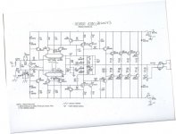
In your schematic, the collectors of your outputs are connected directly to both power rails - the mounting points, including screw holes and heat spreader, of your output transistors, are connected internally to the collector of those transistors.
Artic Silver 5 is for computer heat sinks, NOT amplifier transistors. Regular old silicon thermal grease is just fine - some people even prefer no grease at all and instead use silicon inserts.
Based on the information in your first post, there is something definitely wrong with your method of attaching the heat sink. Conductive paste, bad or missing insulators, missing top hats under the mounting screws. Somewhere, somehow, your heat sink is part of the circuit, and shorting the rails to ground and/or each other.
In your schematic, the collectors of your outputs are connected directly to both power rails - the mounting points, including screw holes and heat spreader, of your output transistors, are connected internally to the collector of those transistors.
Artic Silver 5 is for computer heat sinks, NOT amplifier transistors. Regular old silicon thermal grease is just fine - some people even prefer no grease at all and instead use silicon inserts.
Last edited:
Mike,
A perhaps hidden matter I forgot to mention re checking for shorts is that the heatsinks are anodised - so the layer of black material insulates the heatsink aluminium from the test lead of a multimeter. I assumed you would have covered this point in the tests you made.
If not then you need to find a place on the heatsink or a connection to the chassis earth where there is some bare metal. If you remove a screw securing the heatsink to the chassis you might find bare metal inside the screw hole.
Michael Jonassen
Last edited:
Hey guys, thanks for all the help. Got it back together tonight. It was just the paste. That is why I was unable to find a short. Doesn't show up just probing with meter. I knew everything was assembled correctly and could find nothing out of place. Cleaned all the Artic Silver 5 off ( real pain in the a$$) and replaced with Artic silver Ceramique 2. Good to go. Now I need to find the time to lesten to it and see how it sounds compared to the stock one.
- Status
- This old topic is closed. If you want to reopen this topic, contact a moderator using the "Report Post" button.
- Home
- Amplifiers
- Solid State
- need help - modded amp blowing fuses