And there is a prototype circuit up and running, using a MJL4281A and MJL4302A as output devices and 2x43VDC rails.
When i punish it hard by driving a two ohm load, it distorts badly when it reaches about 10V peak output.
There won't be enough drive current for bjt's I imagine.
Hi
In my latest amp I used for the DC servo comparator a new device called and E-pad from Advanced Linear Devices.......................... The amplifier should be bias without the DC servo to be very close to 0VDC. Temperature will cause minor drift, this where the servo comes in.
Thanks for the link.
These are all areas in the design I need to look at. At the moment it has been as much an exercise in gettig to grips with LTspice as much as anything. And I think I have a total "newb" question on something I can't just figure out which I'll post if I get stuck.
And there is a prototype circuit up and running, using a MJL4281A and MJL4302A as output devices and 2x43VDC rails.
When i punish it hard by driving a two ohm load, it distorts badly when it reaches about 10V peak output.
you need triple EF output
")
Mooly and pergo, indeed, it works but needs some work.
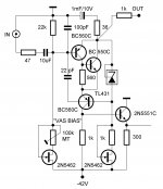
I already had to lower the 15k resistor in the constant current source to 5.6k to get any audio through this thing, and its possible i also have a faulty transistor in there as i used transistors pulled from other projects as i am currently all out on 2N5551's and only have two 2N5401's left.
Atleast the MJL4281 ans MJL4302 proved to be really rugged devices as they lived through the whole ordeal.
This is the current test circuit: http://i.imgur.com/IQPMi.png
http://i.imgur.com/zli3E.jpg
http://i.imgur.com/ireSc.jpg
http://i.imgur.com/zli3E.jpg
http://i.imgur.com/ireSc.jpg
Mooly and pergo, indeed, it works but needs some work.
I already had to lower the 15k resistor in the constant current source to 5.6k to get any audio through this thing, and its possible i also have a faulty transistor in there as i used transistors pulled from other projects as i am currently all out on 2N5551's and only have two 2N5401's left.
Atleast the MJL4281 ans MJL4302 proved to be really rugged devices as they lived through the whole ordeal.
You are so optimistic by using only one input BJT and expect the amp to be perfect
that's why I give you this improved SE input stage to play with. Attachments
LC, you and your obscure and weird parts And a IPs which alone is about as complex as the entire amp feels a bit like more work than it is worth.
If i wanna build the perfect amp, i'll just make use of the LME49810's i have laying around.
Yes my test circuit uses only a single pair of outputs.
And a IPs which alone is about as complex as the entire amp feels a bit like more work than it is worth.If i wanna build the perfect amp, i'll just make use of the LME49810's i have laying around.
Yes my test circuit uses only a single pair of outputs.
LC, you and your obscure and weird parts
This input stage has -3dB/10MHz (without input low pass filter) and it is very, very stable, low noise too.

You cannot compare it to single BJT, performance justify the complexity.

Make it, you will never regret it.
P.S. 2N5551C and 300 ohm are already in your circuit.
Last edited:
If i wanna build the perfect amp, i'll just make use of the LME49810's i have laying around..
hahahaha now you're joking

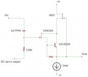
For what it's worth, here is a buffer circuit I use to mix the DC servo output with the signal input so the output of this circuit steers the input stage so that DC out is zero. The KSK595 or similar is a low conductance J-fet designed to be used with capacitor mics and very high Z input stages. It is bias about 20uA or so. If the current source bias is a couple mA, the 4091 should have a Vgs about -6V. With a constant current Id and constant Vds the KSK595 makes a very good linear transfer of the input signal voltage to an input signal current, resulting in a lower Z to drive the first transistor in the IPS. The obvious advantage is being able to use polypropylene for the input cap.
Attachments
Besides i dont have any of those Jfets or that TL431 voltage controlled zener diode or whatever it is anyways.
On top of that, i've never really been a fan of CFP.
Parts are easily available the same as parts you use regulary.
Of course you haven't, you didn't give a proper chance to current feedback yet. What did you expect from single BJT input stage biased with resistors?
And something else, it only takes about a two volt drop in rail voltage in real life for something to completely shut off and not let any audio through.
Not by my input stage, rail voltage doesn't influence working conditions stability, since two CCS defines them.
More than 20 mA VAS bias is not recommended here and that you already passed. The problem you described is caused mainly by the single BJT input stage, not in a position to supply sufficient drive current, plus its working conditions are very unstable.Increasing the current in the CCS cures the distortion and brings the output up to 23V peak on full volume into a 2 ohm load before it starts to distort again.
- Status
- This old topic is closed. If you want to reopen this topic, contact a moderator using the "Report Post" button.
- Home
- Amplifiers
- Solid State
- Bipolar Power Amp With Single Ended Input Stage Inpired by Mooly