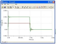
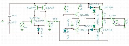
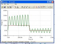
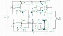
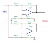
Hello, I could use some help with this op amp with LSK170 inputs. I'm simulating this little op amp and it seems to be fine when used alone but when I parallel them for a push pull arrangement, it oscillates. The gain is the same for both circuits. I don't understand why the single version would be stable at low gain (6dB) whereas the double version is not. The double version is stable at higher gains. I've tried by pass caps around the feedback resistors, as well as other kinds of bypass caps and nothing is helping. Any input is appreciated.
Attachments
My guess that the problem is due to the closed loop output impedance of the amplifiers increasing with frequency as the open loop gain falls.
The open loop output impedance of the amplifier is 27 ohms / 2 plus emitter resistances.
Any transient on the one of the outputs will be only partly attenuated by the open loop output impedance of the other amplifier which will then appear at it's input and be amplified. It must be just enough to sustain oscillation.
At higher gains the attenuation of the feedback is greater so no oscillation.
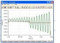
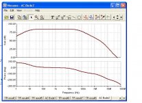
The single version is not very stable with some ringing at about 5 MHz at the input transition. It might be worth looking at the Bode plot of the open loop because there isn't much in the way of frequency compensation.
The open loop output impedance of the amplifier is 27 ohms / 2 plus emitter resistances.
Any transient on the one of the outputs will be only partly attenuated by the open loop output impedance of the other amplifier which will then appear at it's input and be amplified. It must be just enough to sustain oscillation.
At higher gains the attenuation of the feedback is greater so no oscillation.
The single version is not very stable with some ringing at about 5 MHz at the input transition. It might be worth looking at the Bode plot of the open loop because there isn't much in the way of frequency compensation.
I see that you are driving a 1k load on the single amp and a 150 ohm load on the double amp. Increase the load resistance on the double amp to 2k and measure the performance.
Thanks for the suggestion. I just now tried that but it doesn't make a difference. I think it made it worse actually.
Attachments
This arrangement needs unity gain stable amplifiers. The reason is rather subtle, and in the hurry I don't think I'll be able to explain it well. Anyone?
Samuel
I figured that much, thanks. I guess the real question I'm asking is how to make a discrete op amp unity gain stable. It's too subtle for me to figure out on my own.
Why try discrete designs when there are opamps available that does unity gain just fine ?
The NE5532 is an excellent choice, its cheap and has very low THD and noise.
Why sail a 40 foot boat across the Atlantic by yourself when you can fly there in 7 hours?
My guess that the problem is due to the closed loop output impedance of the amplifiers increasing with frequency as the open loop gain falls.
The open loop output impedance of the amplifier is 27 ohms / 2 plus emitter resistances.
Any transient on the one of the outputs will be only partly attenuated by the open loop output impedance of the other amplifier which will then appear at it's input and be amplified. It must be just enough to sustain oscillation.
At higher gains the attenuation of the feedback is greater so no oscillation.
The single version is not very stable with some ringing at about 5 MHz at the input transition. It might be worth looking at the Bode plot of the open loop because there isn't much in the way of frequency compensation.
Thank you! Now I remember! The open loop gain has to cross the 0 dB point before the phase shift reaches -180 degrees. As we can see in this plot, I don't have that in this circuit.
Attachments
why the lack of compensation C - how did you determine the amps are stable, with what margins, loads?
I've found that the SRPP VAS usually doesn't need a Miller capacitor. Sometimes it does though and maybe now would be a good time to install one. Thanks!
Thank you! Now I remember! The open loop gain has to cross the 0 dB point before the phase shift reaches -180 degrees. As we can see in this plot, I don't have that in this circuit.
Thanks for attaching the Bode Plot which is interesting.
I have been using LTspiceIV because it's free and it's OK but I like the presentation of the information by the simulator that you are using. Which one is it?
Thanks for attaching the Bode Plot which is interesting.
I have been using LTspiceIV because it's free and it's OK but I like the presentation of the information by the simulator that you are using. Which one is it?
It's Tina:
http://www.ti.com/tool/tina-ti
This is free also.
Common mode signals will receive full feedback. The gain resistor R8 is ineffective for anything common mode (nothing to divide down when there is no difference signal), therefore the full output signal reaches the inverting input(s).This arrangement needs unity gain stable amplifiers. The reason is rather subtle, and in the hurry I don't think I'll be able to explain it well. Anyone?
Samuel
Common mode signals will receive full feedback. The gain resistor R8 is ineffective for anything common mode (nothing to divide down when there is no difference signal), therefore the full output signal reaches the inverting input(s).
Thanks. I don't know how to fix it. I tried using an output transformer (1:1) to cancel the common mode signals, but it didn't help at low gains (less than 10dB)
You need to make each half of the circuit unconditionally stable for unity gain and expected/typical loads (cables), running individually. Check with a pulse generator (or square waves), if you see any ringing then you must use (more) compensation in the amps.
Once that is fixed, you can use your arrangement with any additional differential gain.
Basically your circuit is the front-end (first two opamps) of a typical 3-opamp "instrumentation amplifier", and those need to be unity stable opamps. Having the common gain fixed at unity while differential gain can be increased is the whole idea behind the common gain resistor. The second stage (the subtraction circuit) then removes the common signal and refers the differential signal back to GND
You need to make each half of the circuit unconditionally stable for unity gain and expected/typical loads (cables), running individually. Check with a pulse generator (or square waves), if you see any ringing then you must use (more) compensation in the amps.
Once that is fixed, you can use your arrangement with any additional differential gain.
Basically your circuit is the front-end (first two opamps) of a typical 3-opamp "instrumentation amplifier", and those need to be unity stable opamps. Having the common gain fixed at unity while differential gain can be increased is the whole idea behind the common gain resistor. The second stage (the subtraction circuit) then removes the common signal and refers the differential signal back to GND
Yeah thanks for your explanation. The instrumentation amplifier was my inspiration for this circuit. I wasn't aware of the unity gain requirement though.
Thanks for the information that the simulator is 'TINA' which I have now downloaded.
Just for infomation and to show off my TINA drawn schematic an alternative differential input differential output circuit is shown in 'Applications of Operational Amplifiers' by Jerald G. Graeme.
Attachments
Thanks for the information that the simulator is 'TINA' which I have now downloaded.
Just for infomation and to show off my TINA drawn schematic an alternative differential input differential output circuit is shown in 'Applications of Operational Amplifiers' by Jerald G. Graeme.
Hmmm, interesting circuit. thanks!
- Status
- This old topic is closed. If you want to reopen this topic, contact a moderator using the "Report Post" button.
- Home
- Amplifiers
- Solid State
- Help with push pull opamps