Hi everybody,
I'm waiting for a pair of boards from the store and in the meantime I'm doing part selections (based upon the offcial BOM) from my local resseller (TME in Europe).
Can you tell me if I'm not making wrong choices here?
Q1-Q2: anything else than mpsa18 and ss9014?
Q16-Q18: 2SC5200
Q19-Q21: 2SA1943
Q14: 2SC4793
Q15: 2SA1837
Q11-Q13: MJE340STU
Q10: MJE350
Q3,Q4,Q7,Q8: BC550CTA
Q5,Q6,Q9: BC560CTA
D3: 1N4744A-FAI
D4,D5,D8,D9: 1N5408RLG
R7: 3296W-1-201LF BOURNS
R30: 3296W-1-501LF BOURNS
R17: 3296X-1-102LF BOURNS
R37-R42: MPR5W-0R22 (non inductive and seems like the legs shall be long enough to fit the board)
R49,R50: 3W-10R MOR03SJ0100A19
Other res and capacitors are quite straightforward so I'm not listing them here.
I'll be using Diyaudio PSU boards with 4x 10000uf 100V each and maybe a couple of 300Va 45V+45V trannies (Toroidy). I'm going the pure dual mono road.
As Q1-2 I use ss9014c and these work very well. As for VAS transistors these should have very low capacitance and be fast enough. MJE340/350 are not so good in these areas. Use ksa1381/ksc3503 as in the original HB or similar. I use 2sa1209/sc2911. For bias I use ksc2690ay but MJE should work OK here.
cheers,
I'd do what the build guide says. Check your work. Compare the voltages in your build with those given in one of those schematics used for Spice (screenshots are floating around the web).
I am pretty confident I didn't mess up this time (checked and re-checked) but I will sure post some pictures later today.
I didn't know we had Spice project files for Honey Badger. That would really help! Could someone with the files PM me (I will give you my email)? Thanks!
I just realized that the build guide's comment about 0.5V on 10 Ohm fuse resistors applies to the initial state of the amp (when there is no bias set yet). So I turned bias off and naturally the voltage across the fuse replacement resistors went down to under 0.5V. Great!
Tested the first board today all the way up to connecting the speaker and playing a few tunes. The sound is great! I really love it!
When I connected the second board the voltage across 10 Ohm resistors jumped WAY up and so I went and checked what is wrong. At the same time one of the power transistors started heating up (much more than others). I replaced that transistor with a spare and following power up and test went very smoothly.
So now I have two working boards. The next step is mounting power/output/input terminals and adding a slow start board.
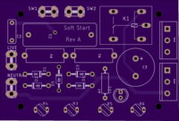
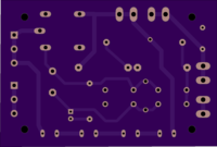
For the slow start, I decided to go with my own PCB design and use essentially the same schematic as what is offered for sale at the diyAudio store with just one difference: replace the 4 power resistors with 4 NTC thermisters (serially connected, 10 Ohm each). As the result, the board came out smaller (77mm by 55mm), the same size as one of the sections with rectifiers from the universal PSU board I got from diyaudio store. The plan it to use 60mm brass standoff spacers and mount it on top of PSU (I really don't have much room left elsewhere, my chassis is 3U size).
Just ordered the PCB and the parts last night. Will post the results once I get it back. I used Eagle CAD for design and Oshpark for fabrication.
Tested the first board today all the way up to connecting the speaker and playing a few tunes. The sound is great! I really love it!
When I connected the second board the voltage across 10 Ohm resistors jumped WAY up and so I went and checked what is wrong. At the same time one of the power transistors started heating up (much more than others). I replaced that transistor with a spare and following power up and test went very smoothly.
So now I have two working boards. The next step is mounting power/output/input terminals and adding a slow start board.
For the slow start, I decided to go with my own PCB design and use essentially the same schematic as what is offered for sale at the diyAudio store with just one difference: replace the 4 power resistors with 4 NTC thermisters (serially connected, 10 Ohm each). As the result, the board came out smaller (77mm by 55mm), the same size as one of the sections with rectifiers from the universal PSU board I got from diyaudio store. The plan it to use 60mm brass standoff spacers and mount it on top of PSU (I really don't have much room left elsewhere, my chassis is 3U size).
Just ordered the PCB and the parts last night. Will post the results once I get it back. I used Eagle CAD for design and Oshpark for fabrication.
Last edited:
NTC's are safer in case of amp failure at startup (fuses will engage sooner). They are safer in case relay fails to engage (the amp will just work, no smoke and fireworks from blown power resistors). They also take less room on PCB (this was crucial for me) and cost about the same.
Hi AudioSan,
How the devil do you weld relay contacts by using a normal resistor??? This points to using an inappropriate resistor value for the job at hand. 40 years in service and I have yet to see relay contacts damaged because of a slow start resistor. The only other variable is time to close the contacts if it is too quick, but your assertion that using NTC resistors cures the problem suggests that isn't the problem. An NTC resistor takes some time to heat up and reduce it's resistance.
-Chris
")
Hi reedcat,
Neat layout, but the image is small for the old, blind folks amongst us ... like me.
-Chris
Yeah, sorry about that. Sometimes when I post a bigger picture all I get is a link that says "Click the image to open in full size" but when you click nothing happens, just a spinner. Like this post #207 here:
http://www.diyaudio.com/forums/powe...er-snubber-bellringer-jig-21.html#post5185054
the relay that bypasses the soft start resistors has very little stress. It has no duty to perform at switch off when the main sparking across an opening contact occurs.My biggest + for going for NTC's is that you don't weld the relay when it kicks in. that is a problem i had i few times with resistors.
It is open at start up and because the resistors limit the start up current there is little happening around the relay contacts. After the pre-set delay the relay closes to bypass the resistors, but by then the transformer is active and the change in current as the bypass closes is very small.
For the above reasons, you will find that a 2A 250Vac relay will last almost forever in bypass duty, no matter how big, or small, your main transformer is. If you want to be ultra safe you could use a 5A 250Vac relay (It will still be working when your grandkids grow up).
BTW, the 2A rating of the relay contacts is the current breaking capacity of the relay. this would normally limit you to ~460VA on a 230Vac supply
These relays will usually pass AC currents much higher than that in a continuous duty. I have had long life bypassing on a 1000VA transformer.
The bypass relay as stated earlier does NOT have to break the main transformer current at switch off.
Last edited:
use the attachment instructions given here:Yeah, sorry about that. Sometimes when I post a bigger picture all I get is a link that says "Click the image to open in full size" but when you click nothing happens, just a spinner. Like this post #207 here:
http://www.diyaudio.com/forums/powe...er-snubber-bellringer-jig-21.html#post5185054
How to attach images to your posts.
Hi AudioSan,
How the devil do you weld relay contacts by using a normal resistor??? This points to using an inappropriate resistor value for the job at hand. 40 years in service and I have yet to see relay contacts damaged because of a slow start resistor. The only other variable is time to close the contacts if it is too quick, but your assertion that using NTC resistors cures the problem suggests that isn't the problem. An NTC resistor takes some time to heat up and reduce it's resistance.
-Chris
powerfull class A will do the jobb. in my case, it was the aleph2 monoblocks.
Hi AudioSan,
Still shouldn't happen. There is something wrong with the component values or the circuit. No way should the shorting contacts get burned in a relay unless it was a tiny one (serves you right in that case). The NTC parts can get quite hot, which is why the resistance drops so far down. If you had the wrong value of surge resistor, a NTC would cover the mistake up just because it is variable.
-Chris
Hi AudioSan,
That relay would be perfectly fine. It really comes down to resistor value and time to kick in. For large power supplies like that, the resistor is normally something like a Dale that bolts onto a heat sink - like the chassis for example. The relay has to remain open long enough for the supply to partially charge enough so there isn't a large surge. Seeing a 10 or 20 watt resistor bolted to a heat sink / chassis is not an unusual sight in commercial amplifiers. So allow the resistor to dissipate heat. It simply limits the peak charging current, so size the resistor for whatever value you see as being reasonable. Then allow the relay to remain open long enough to charge the supply to some level that won't be destructive to the relay. Make sure the resistor can handle that much heat and peak current. Generally speaking, the metal resistors with a flat mounting surface do have a generous current rating.
Given the power supply has an obscenely high capacitance, you may end up with a larger surge resistor on the order of 50 watts. The one factor in your favour is that the operation is temporary and it will cool off nicely. That means that you can exceed the steady state power rating for a short period of time, but watch the peak current specification! These circuits are extremely reliable in normal use and I've never had to replace a power switch or bypass relay in these circuits. The thing is, you have to design the soft start circuit in relation to your supply. Clearly, in your case, "soft start" is a relative term. Your initial surge may possibly dim the lights a little, as opposed to tripping the breaker when you turn that beast on. Personally, I think the capacitance is too high. Excessive filter capacitance is not your friend.
-Chris
1000VA on a 230Vac supply is only 4.3Aac when at full power.
You should be fitting a close rated mains fuse of either T5A or T4A.
To ensure these don't rupture at start up you need to add in a current limiting resistor.
I have found that twice the start up surge current does not rupture the fuse. I think I recall that others have gone as high as three times the fuse rating and found no nuisance blowing in the longer term.
Using my 2times, you should be aiming for 8Aac or 10Aac. Using 3times you could be as high as 12Aac to 15Aac.
Let's for the sake of an example take 10Aac as the reliable limit for a T4A mains fuse.
for 230Vac & 10Aac you need the primary circuit to have a total resistance of 23ohms.
If your primary is 0.7ohms and you wiring is 0.1ohms then you need an added resistance of 22.2ohms
Try 22r and see if your mains fuse survives many cold restarts.
A 50W 22r power resistor has a maximum continuous rating of 1.5A
the surge overload rating is likely to be around 3A
But you will be passing a maximum of around 10Aac for a bit less than half a mains cycle, about 4ms.
I prefer to use many series connected power resistors with lots of thick resistance wire inside to give a high tolerance to overload for this very short period.
Last edited:
- Home
- Amplifiers
- Solid State
- diyAB Amp The "Honey Badger" build thread