The kapton tape I have used has no adhesive. The thermal compound is needed to thermally couple the transistor to the kapton tape and the kapton tape to the heatsink. If your kapton tape has adhesive, I am not familiar with its application or if the adhesive also functions as the coupling medium. Maybe someone else here has some info?
the adhesive is used alone on one side of the Kapton tape.
I have used a variety of tapes with adhesive on one side for electrocal insulation.
I have found, on dismantling, that the adhesive flows from the (high pressure, hot area) interface to the edge of the device where a bulge of spare adhesive builds up.
The result of this is that the adhesive trapped in the interface becomes thinner as time under pressure proceeds. This requires a re-torquing of the clamp bolts.
And after re-torquing you will find that interface performs very slightly better thermally.
This also applies to the "Koptan" tape I bought very cheaply. It performs admirably. Almost as good as thin mica.
Thanks Andrew, you always have awesome advise which really helps and is very much appreciated.
You timing was perfect. I have now just applied the thermal paste and secured the output transistors. One channel is complete.
Thanks again...

You timing was perfect. I have now just applied the thermal paste and secured the output transistors. One channel is complete.
Thanks again...
Attachments
Last edited:
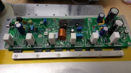
Chassis layout
Went with a smaller case, had to split the PSU board into sections. There is still some room between the transformer and the amplifier boards. I plan to use it to (vertically) mount soft start and speaker protection. Any comments?
Went with a smaller case, had to split the PSU board into sections. There is still some room between the transformer and the amplifier boards. I plan to use it to (vertically) mount soft start and speaker protection. Any comments?
Attachments
Went with a smaller case, had to split the PSU board into sections. There is still some room between the transformer and the amplifier boards. I plan to use it to (vertically) mount soft start and speaker protection. Any comments?
Looks ok to me.
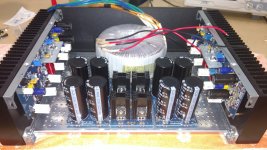
Instead of the rectifier diodes and heatsinks I used rectifier blocks to save a lot of space (add a snubber and you'll get the same smooth switching performance). I also mounted the smoothing caps closer to each other (not using the diyAudio PSU boards). The additional space allows for more additional smoothing caps. There was still enough room for the slow start, and the speaker protection went to the back plate. See photos here.
Hi reedcat,
Does your build consist of single transformer with dual secondaries, 2 independent PSU and 2 amps?
regards
Prasi
One transformer, dual secondaries, just enough to feed one dual rail PSU, two mono amps (one on each side).
The extra wires from the transformer are another set of smaller voltage/wattage secondaries which I don't use at the moment.
Last edited:
Shielded Cable
Quick question.
Now that I have a better understanding if ground loops, I re-wired my Honey Badger to get rid of the noise my poor grounding scheme was causing. I successfully eliminated all hum/buzz from one channel, but still had some in the other.
After checking everything, I realized all the cables leading to my Soft-Start board were very close to (touching) that channel's outputs. I moved the board as far away as I could put it, and the noise was greatly reduced. But I can't move the Soft-Start board far enough to get rid of all the noise -- the board is still very close. So I'm looking into shielded cable for the outputs.
Is there anything special I should look for?
Last edited:
...The additional space allows for more additional smoothing caps. There was still enough room for the slow start, and the speaker protection went to the back plate. See photos here.
Very nice build! Would you like to share which boards/design you used for PSU, soft start and speaker protection?
Very nice build! Would you like to share which boards/design you used for PSU, soft start and speaker protection?
I made my own PCBs for the PSU caps, which was a bit too much effort for this one-off build. Next time I'd probably use screw-terminal caps and thick copper bars instead of a PCB.
Soft start and speaker protection are both from eBay. However, I'd recommend to take a look at the 21st century soft-start / speaker-protection board. I made a strong effort to keep the audio GNDs of the two channels separted from each other and from safety earth. To keep the audio GNDs separate, I had to use separate speaker protection units, and I had to trick'n'tweak them to be able to run them off the same helper power supply without connecting the GNDs via the power supply. The 21st century board should be better/cleaner in this respect.
Thanks for the tip but i already purchased soft start and speaker protection, PSU will most probably be screw in terminal caps. I'm just trying to figure out how to fit everything in the 4U chassi since I'm planning to do a complete dual mono system(maybe a foolish plan in this chassi..). Your speaker protection looked so well sized i had to ask about it ")
I'm just trying to figure out how to fit everything in the 4U chassi since I'm planning to do a complete dual mono system(maybe a foolish plan in this chassi..).)
You should be able to fit dual mono Honeybadgers into a 4U chassis easily. It just takes some prior planning. Look how Filenet did a dual mono NS-OPS in his 4U chassis. It looks full, but it's very serviceable. Revisiting some "old" ideas from 1970's - IPS, OPS
- Home
- Amplifiers
- Solid State
- diyAB Amp The "Honey Badger" build thread