Mine behaves somewhat the same. I run a bit hotter than 50 mA, and both bias and offset take a while to settle. My sinks run about 18°F above ambient. Q13 is mounted directly to the sink in a store 4U case. I think it stabilizes faster than 30 minutes, but it was at least 15-20 minutes when I was measuring. Offset never got above 15 mV and settled at < 1 mV, so I didn't worry. Sound quality seems to be consistent from turn on to fully settled.
Consider a trying a DC blocker - you could be getting a bit of DC on the line.
most likely, this the reason i resist the temptation to use torroids, i am strictly an EI traffo kind of guy......

Finally got my badger fully up and running.
Finally got my Badger fully up and running. I am most happy with the result! I am hearing sounds in songs that I swear weren't there before!
I tested it on a dummy 4 ohm load up to approx 250W output. I bought a nice big 300w resistor so I could safely test it. I couldn't push it any further to see when clipping started because I don't have a scope here to see the waveform.
I am using +/-58 VDC dual mono 480VA traffosX2 & 24000uF/rail for each channel. I have the bias set at 50ma/device. My heatsink is from an old school 600W Kenwood car amp. It barely warms up at idle and should be more than sufficient.
Thank you OS for the design and the help!
I guess I spoke a little too soon. It seems I might be having a slight thermal runaway issue. My 25mv (50ma per device) bias has reached 35mv . My heatsink was running about 30 degrees farenheit over ambient at that point. I was not using the amp loudly at all and was not averaging more than a couple watts all night
Shouldn't the thermal compensation be keeping my bias very close to my original settings?
Shouldn't the thermal compensation be keeping my bias very close to my original settings?
I have attached my BoM for the Honey Badger, as a Mouser shared cart available at the URL below. Note that for me at least this is based on Australian pricing.
http://www.mouser.com/ProjectManager/ProjectDetail.aspx?AccessID=8080aaf520
Hi Wembley
I assume that this is just one channel ???
I clicked on your link and Mouser comes back with $ 69.50 USD.
The following 2 items are out of stock
KSA1381ES Transistors Bipolar - BJT PNP Epitaxial Sil
SS9014CTA Transistors Bipolar - BJT NPN/50V/100MA
KSA1381ESTU is available to replace the PNP, is it suitable ?
and for the NPN 512-SS9014CBU is available, again I ask if this is a suitable replacement.
Regards
Simon
I guess I spoke a little too soon. It seems I might be having a slight thermal runaway issue. My 25mv (50ma per device) bias has reached 35mv . My heatsink was running about 30 degrees farenheit over ambient at that point. I was not using the amp loudly at all and was not averaging more than a couple watts all night
Shouldn't the thermal compensation be keeping my bias very close to my original settings?
Thermal compensation will stabilize bias, but not necessarily where you set it with the sinks not thermally stable. How did you set your bias? If you turned it up to 25 mV right away it will continue to increase a bit as the sinks heat up. I set mine to 16 mV and after a half hour of heating up was up close to 30. It then took a few cycles of heating and cooling to get the bias to stabilize where I wanted it. Once there it's stayed steady.
Thermal compensation will stabilize bias, but not necessarily where you set it with the sinks not thermally stable. How did you set your bias? If you turned it up to 25 mV right away it will continue to increase a bit as the sinks heat up. I set mine to 16 mV and after a half hour of heating up was up close to 30. It then took a few cycles of heating and cooling to get the bias to stabilize where I wanted it. Once there it's stayed steady.
OK that sounds reasonably close to what I am experiencing. I am now at 25mv at this (warm) temp. I am keeping an eye on my heatsink temp at its warmest spot to see if it has leveled off. It seems to be holding firm idling at ~27F over ambient.
Since I am getting this warm at idle, I am worried that the heatsink might not be quite enough. Does this sound reasonable for a heatsink temp at idle?
At 50ma per device, 150ma total X 58VDC X 2 = 17.4watts. Doesn't seem like my heatsink is going to be able to do the job if 17 watts is bringing me 27F over ambient!
PS for HB
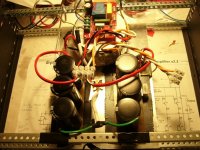
My PS for HB (attached) gave me a puzzle to solve. Yesterday I powered it up via a globe and soft start and everything worked fine. I switched it off and switched on again and suddenly my 75W globe is shining brightly. So I switched it off and it appeared that coil in soft start relay was burned.
I replaced soft start with another module, powered it up and the globe is shinning brightly again. This time coil is not burned. I disconnected capacitor banks and bridges, switched PS on, globe stayed dark and toroid gave me 2x47AC no load which is fine. I reconnected bridges, the same thing, all is fine and on each bridge I get about 44.5V DC (- to +), which seems fine.
I measure capacitor banks, each has 41.5mF which is roughly the right figure. 5W resistors are about 0.22 and fine. I haven't reconnected capacitor banks yet. Burned MURs860? But with no load they do not conduct. What could go wrong?
cheers,
Attachments
Definitely something went wrong for some reason. This PS worked fine within the first test lasting a number of minutes. It only sudenly failed when I switched it on for the second time after switching it off. Nothing was really changed in between tests except for the switch connection but the switch is OK. I'll post some photos when I get home after work but I do not know if they will help.
cheers,
cheers,
Thanks AJT,
Soft start switches the toroid on after a few seconds. Resistors on rails form CRC circuit and diodes take over for higher currents - see ostripper's PS for HB.
I tested everything again. Each bank of caps connected to its bridge works fine giving about 64V. Problem appears when I connect positive (+) and negative (-) of these two capacitor banks together to form the common ground. Then the globe is on and the soft start does not switch on. But it worked before and it should. So something went wrong but what?
I may try a standard solution: one 50A bridge, secondary windings centre to the ground but again positive and negative capacitor banks' rails have to be common and connected to the common ground.
Before that I may also try connecting the common ground point, which is on the chassis, to the mains ground and see what happens.
Any ideas? Are there any known problems with this kind of PS?
Thank you,
cheers
PS a few images attached, these green cables are to connect both banks to the common ground,
Attachments
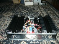
definitely a wiring mistake, i also used the same psu topology as yours in my badger build,
i did not use a soft start board....only a speaker protector board....
perhaps if you can have someone look at your work he may be able see something that
you might have missed....the picture you posted is no help to me either, sorry...
the cap bank can be in a single board with common ground trace...
I'll ask a friend of mine to take a look at it during the weekend but I do not think there is any wiring error as it worked without any problems and nothing has really changed since then. The only difference is that soft start switch is now hard wired, while before it was connected to a switch, which might have created this problem but I have no idea what happened.
Theoretically, there may be a problem with my soft start unit but I checked all its components. With caps centre rails connected to the ground it does not switch on. I have such soft start unit working perfectly well switchin on two 300VA toroids. Toroid in this PS is 500VA.
cheers,
Theoretically, there may be a problem with my soft start unit but I checked all its components. With caps centre rails connected to the ground it does not switch on. I have such soft start unit working perfectly well switchin on two 300VA toroids. Toroid in this PS is 500VA.
cheers,
this is too low........... powered it up and the globe is shinning brightly again. This time coil is not burned. I disconnected capacitor banks and bridges, switched PS on, globe stayed dark and toroid gave me 2x47AC no load which is fine. I reconnected bridges, the same thing, all is fine and on each bridge I get about 44.5V DC (- to +), ..............,
A 47 plus 47Vac dual secondary transformer should give ~65Vdc on each capacitor bank.
Under light load expect 1V to 2V less.
this is too low.
A 47 plus 47Vac dual secondary transformer should give ~65Vdc on each capacitor bank.
Under light load expect 1V to 2V less.
If he has only the bridge hooked up without the filter caps it would read about 47Vdc. I wonder if maybe he has crossed the secondary leads somehow and doesn't have them hooked up properly to the bridges.
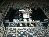
EDIT; After looking at the pictures, with the softstart circuit mounted on top of the torioid I wonder if maybe he has created a ground around the transformer. Make sure that there is no ground connection formed to the transformer mounting bolt.
Last edited:
Thanks for help,
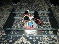
There is no ground connection to the toroid. Soft start is perfectly separated from the chassis and everything apart from mains connections via the globe and the output going to the toroid.
I tested a number of different bridges (35A and 50A variety) on different transformers. All behave exactly the same way. Voltages differed as transformers used were 2x25V, 2x40V and 2x45V nominal.
When this PS was switched on for the first time and worked, AC voltages were about 47V (toroid is nominal 2x45V 500VA) and DC voltages were about 64.7V. I've just measured voltages again with capacitor banks not grounded. AC on each winding is about 49.4V and DC on each bank is exactly 66.67V on each. Bleeding resistors are the only load.
I'm becoming suspicious of that soft start unit. It is not grounded and possibly it should be. I have to ask Stanton from Jims_audio. But then why did this PS work fine when switched on for the first time?
I have to by pass soft start and connect toroid to the mains only via the globe and see what happens. Any other ideas?
cheers,
Two things I can think of to try/test. First is to measure between the two banks of filter caps without them connected together. The second thing is to try reversing the secondary wires from the transformer on one of the bridges only. It may be that you are out of phase.
In the pictures it looks like the soft start in bolted directly to the torioid mounting washer on one end and the chassis frame on the other. If the mounting bolts are electrically connected to each other that would cause loop. Just something to check. You did say that it worked before you installed the soft start. Easy way to check is to remove the mounting bolts on the soft start and see if the problem goes away.
Blessings, Terry
There is no ground connection to the toroid
In the pictures it looks like the soft start in bolted directly to the torioid mounting washer on one end and the chassis frame on the other. If the mounting bolts are electrically connected to each other that would cause loop. Just something to check. You did say that it worked before you installed the soft start. Easy way to check is to remove the mounting bolts on the soft start and see if the problem goes away.
Blessings, Terry
Last edited:
I'm not sure that's a true statement. The capacitors don't cause the voltage to increase from the secondary windings, it's the rectifiers. That is if IIRC from my electronics training some 45 years ago.If he has only the bridge hooked up without the filter caps it would read about 47Vdc. ...
I don't think rectification principles have changed any since then. Secondary voltage * 1.414 will give you the DC voltage of the PSU - under light-to-moderate loads. That's a fairly standard calculation, but not the only one to consider. The caps just are used to filter the DC voltage and hold a charge when sudden bursts of current (load increase) may be required by the amp. That's why they should be rated at a minimum, higher than the expected rectified voltage. In fact, the higher the voltage rating on the smoothing caps the better. Only disadvantage is size and cost.ESP has much more to say on the subject here.
- Home
- Amplifiers
- Solid State
- diyAB Amp The "Honey Badger" build thread