How important is it to heat sink Q11&12? Can I leave them on the current heatsink I made, or should those too be mounted to the chassis heatsink?
Both scenario's will work , but having the drivers on the main heatsink will be
superior for high current use.
With the drivers on a small separate HS , the amp will be a slightly overcompensated thermally , as well. (This would require a small change in
R28 ...)
OS
Having a dilemma concerning the power supply.
Transformer has 2 secondarys (Antec8445), I have 2 35 amp bridges.
Monoblock type supply, having one bridge per amp? Or have one bridge
provide + and one provide - and split the output to the two amp boards?
What if any, differences could be expected from the two differing scenerio's?
Transformer has 2 secondarys (Antec8445), I have 2 35 amp bridges.
Monoblock type supply, having one bridge per amp? Or have one bridge
provide + and one provide - and split the output to the two amp boards?
What if any, differences could be expected from the two differing scenerio's?
Having a dilemma concerning the power supply.
Transformer has 2 secondarys (Antec8445), I have 2 35 amp bridges.
Monoblock type supply, having one bridge per amp? Or have one bridge
provide + and one provide - and split the output to the two amp boards?
What if any, differences could be expected from the two differing scenerio's?
An-8445 has two separate 45V secondaries , but you will be using both for
a 90V secondary with a center tap. That would be green/blue together = centertap (CT) , the other green and blue are the 2 AC inputs to your bridge(s).
The ideal is to have the two bridges output 60-0-60VDC separately to each amp
with each amp having it's own separate + and - rail capacitors.
OS
Hi Guys,
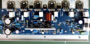
I'm running into a problem firing up my amp boards and hope you can point me in the right direction. I've got my chassis built and dual mono PSU installed and working correctly. I've got 63 VDC rails out of the PSU's. I've adjusted R7, R17, and R30 on accordance with the build guide, R7 set to 85R, R17 to 500R, and R30 to 500R. I have checked all of the transistors on the heat sink to make sure there is no continuity, all are properly insulated. I'm seeing the same exact issue with both boards so I must be a symetrical screw up. When I hook up V+ and V- to the amp board, the V+ led lights, but the V- led doesn't. and I'm reading 2.7 VDC across each of the two temporary 10R resistors across the fuses on both boards. The fuses get warm but haven't burn't up yet since I quickly disconnected everything. I've attached a picture of my board. Any Ideas would be greatly appreciated.
Thanks,
PJN
Attachments
Sounds like you may have inserted the V- LED backwards.
You are getting about 270 mA draw. As the guide says, check your work. To me that says you haven't got output transistors in the wrong spots (it would be instant smoke with 63V rails), but check anyway. You may have the wrong values in the Vbe multiplier, R28 and R29. That might be turning your outputs on too hard.
A way to check the front end without pulling the output transistors is to connect test leads from the bases of Q14 and Q15 to the end of R43 and R46 closest to the bottom of the board. That prevents the output from turning on and closes the feedback loop. If you do that and still see any significant voltage across the fuse resistors, you have a front end issue. If you can set up the front end with the jumpers your issue is the output stage or Vbe multiplier.
Hi Guys,
I'm running into a problem firing up my amp boards and hope you can point me in the right direction. I've got my chassis built and dual mono PSU installed and working correctly. I've got 63 VDC rails out of the PSU's. I've adjusted R7, R17, and R30 on accordance with the build guide, R7 set to 85R, R17 to 500R, and R30 to 500R. I have checked all of the transistors on the heat sink to make sure there is no continuity, all are properly insulated. I'm seeing the same exact issue with both boards so I must be a symetrical screw up. When I hook up V+ and V- to the amp board, the V+ led lights, but the V- led doesn't. and I'm reading 2.7 VDC across each of the two temporary 10R resistors across the fuses on both boards. The fuses get warm but haven't burn't up yet since I quickly disconnected everything. I've attached a picture of my board. Any Ideas would be greatly appreciated.
Thanks,
PJN
I looked ... are the drivers isolated ? I see large washers on them ??
The VAS heatsink looks like it is "ON" the V+ rail . This could be my angle on the photo.
OS
I looked ... are the drivers isolated ? I see large washers on them ?
OS
Pretty sure those are soft plastic washers.
PJN were the leads long enough on those small drivers to mount to the heatsink as you did, with enough for standoffs?
Also OS, I think you recommended grounding the heatsinks. The ones with the 5U Deluxe Chassis are anodized. Should I sand off the finish and ground to that, leave it unfinished...?
Last edited:
Pretty sure those are soft plastic washers.
PJN were the leads long enough on those small drivers to mount to the heatsink as you did, with enough for standoffs?
Also OS, I think you recommended grounding the heatsinks. The ones with the 5U Deluxe Chassis are anodized. Should I sand off the finish and ground to that, leave it unfinished...?
Never saw a "5u deluxe chassis"
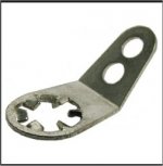
 ..... a star washer lug (below) should dig through
 the anodization with enough torque.
Semi-tighten it .... move it around with pliers - then fully tighten it.
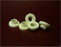
BTW - (below 2).. are the correct driver washers.
OS
Attachments
Last edited:
Hi Guys,
I had the chance to check the resistor values and found eight of them that were way way off. This is a tough lesson, I didn't check every value when I put them in, I assumed that Digikey would include the correct values, boy was I wrong. It's time to get the correct values and install them. Thanks for your help.
PJN
I assumed that Digikey would include the correct values, boy was I wrong.
PJN
I've had the same problem with Mouser. Some times they send me an item completely unrelated to what I bought. But sometimes it's a resistor with the wrong value. Very frustrating.
Quick question: When using the soft star board, is it necessary (or recommended) to use thermistors when connecting the dual primaries in parallel or one of the line-in legs (to ground) prior to the soft start for 120V? I was looking at the F5 build guide and this was depicted... By the way, this is for the Honey Badger...
No, you don't need an NTC and a soft start for the Honey Badger.
The purpose of the NTC in the F5 is to provide the soft start. Class A amps draw high current all the time so the NTC has low resistance in normal operating conditions. The class AB Honey Badger will not draw high current until it is running at high power, so you want to get the resistance out of the way once the turn on surge is past with a soft start.
There is a school of thought that says NTCs are better than regular resistors in the soft start circuit because they won't burn up if the relay fails to operate. You would put them in place of the resistors - do not parallel, just use one or place them in series.
No, you don't need an NTC and a soft start for the Honey Badger.
Thanks Bob! That makes sense but wanted to make sure that wasn't inferred somewhere that I missed...
I have seen a couple of different opinions on the VBE multiplier. Is there an advantage to the bus bar (besides extra heat dissipation)? Or for that matter, an advantage to mounting the VBE multiplier to the top of the bus bar? I have mine mocked up directly to the heat sink now and want to make sure before I lay down some solder. I would rather not struggle with the de-soldering tools...
Thanks!
Jason
Thanks!
Jason
You're better off the way you have it. You want the Vbe multiplier to sense device/heat sink temperature to prevent thermal runaway. On the buss bar (I assume you mean a bar used to clamp all the output devices to the sink.) There is significant risk that the sinks will heat up and the outputs run away long before the bus bar notices the heat.
Bob, that is exactly what I mean. The build guide shows the bus bar clamping down on the top of the outputs and the VBE multiplier mounted on top of the bus bar. I remembered someone suggesting that the VBE multiplier would be better on the main sink. I will mount them to the heat sink right in between the outputs.
Thanks again!
Jason
Thanks again!
Jason
- Home
- Amplifiers
- Solid State
- diyAB Amp The "Honey Badger" build thread