What's your time worth setting it up? Why not just buy the boards from the store? There aren't many left in this batch, better hurry!
The diyAB "Honey Badger" Class AB Power Amp - 150W/Channel (2 Channels) - Power Amplifiers - Circuit Boards
The diyAB "Honey Badger" Class AB Power Amp - 150W/Channel (2 Channels) - Power Amplifiers - Circuit Boards
Gerber
Hi
Uk store has shut down I believe, and my bro does it where he works so my setup time is nil I guess. He didn't seem to think it was a big issue, we used to do it old money, u know, permanent marker, chemicals, bad etching etc.
Anyway, be a lot cheaper this way...
Thx
Hi
Uk store has shut down I believe, and my bro does it where he works so my setup time is nil I guess. He didn't seem to think it was a big issue, we used to do it old money, u know, permanent marker, chemicals, bad etching etc.
Anyway, be a lot cheaper this way...
Thx
Hi Guys,
I'm populating my boards and have come to a road block. I read this in the build docs.
"The cascode (Q3-4) can be setup in 2 (or more) ways.
- The first is a zener referenced design - omit R18 , replace
with a 1/2w- 1w 12-15V zener diode and set jumper pad "C" to "Z" with thin wire. The "CRZ" jumper pads
are located above D1-2 near "OFFSET". You will have a cascode reference of either 12 or 15V , depending
on Zener diode choice.
- The second way is to use the "luxman" way ,a crude resistive design. R18 is left as is (NO D3) , jumper "C"
will bridge to "R". This will set the cascode reference to roughly 1/3 of the supply voltage ... whatever that is."
Man I hate choices. That's why I eat at buffets, I don't have to tell a waitress what I want.
I used MPSA06 for Q1/2 because I had a bunch of them and I had already matched them. Anyway my question is should I go with the zener or resistor?
Thanks, Terry
Terry, The zener referenced version is somewhat similar to the way your Leach amp is set up, although in the Leach the zener references to ground and here it references to the tail of the LTP. Some say the tail is the proper place to reference a cascode. However, none other than Nelson Pass has used the "crude" way. Look at the F5T V3
Either try something completely different and go crude, or see if you can tell the subtle difference between a ground referenced cascode and a LTP referenced cascode. Either way you can't go wrong. Sounds like OS likes the LTP referenced zener version.
To throw another option in the mix, you can make a header at the CRZ jumpers and go back and forth - do you like your cascode referenced to ground or the LTP? Do the same and put either the zener or resistor in the circuit. Four variations to listen to.")
Either try something completely different and go crude, or see if you can tell the subtle difference between a ground referenced cascode and a LTP referenced cascode. Either way you can't go wrong. Sounds like OS likes the LTP referenced zener version.
To throw another option in the mix, you can make a header at the CRZ jumpers and go back and forth - do you like your cascode referenced to ground or the LTP? Do the same and put either the zener or resistor in the circuit. Four variations to listen to.
Do you want me to make the choice for you?
Then I would go with the Zener referenced Cascode.
Please explain why.
Thanks
Because it works at holding the Vce of the input pair more steady and holds the capacitance seen at the input lower, than no cascode.
The Honey Badger was deliberately designed to allow choices.
You will have quite a few more to make before you complete.
You can make informed choices, but to do that you have a lot of background reading/learning to do. Or you make "guess" choices and accept the outcome.
There is another method. You build all the versions and compare the outcomes to become informed and then you make an informed choice of which you want to build copies of for your long term enjoyment.
You choose.
Last edited:
Hi Andrew,
As you know, I have very limited electronic background. Perhaps this amp was not the best project for me to tackle. Seems it was designed for folks with lots of experience who want to experiment. I juust wanted to build a good sounding amp that was based on the blameless and these looked like nice boards. I have basically followed the BOM and selected parts based on what I already had on hand, which were a lot of Onsemi parts. My boards are populated except for R18/D3. If you say D3 is the better way to go I can surely do that. What would be better, 12V or 15V?
Thanks, Terry
The balance between simplicity and options is very difficult. The Amp Camp kit in the store certainly appears simple to construct, doesn't even require building a power supply, and comes with all the parts. However, the Honey Badger is much more powerful and flexible in design- not to knock the AC amp because it's beauty is its simplicity.
I too am limited in my experience and have had some difficulty with the HB mainly in parts selection. The ideal solution, for me anyway, would be a version of the build guide and BOM that provide pre-selected parts based on one basic design, including PSU, speaker protection and soft start, with wiring diagrams and suggested enclosure layout. That's a big project though. I am more than happy to volunteer my time with document creation, layout, etc but I don't have the tech expertise to write it.
Regarding 12v vs 15v, this was OS's response to my same question. I went with 15v, basically taking the middle road.
You can use 12 , 15 or 24V as D3 - unless you have a real low Vceo LTP pair.
12 or 15 V would cover almost any BJT pair.
Nice trafo - would be a 63-65Vdc rail , perfect for some real exciting transients.
OS
You could use any 20V zeners leftover from your Leach superamp build, too.
The zener referenced version is the technically correct way, but OS allowed for other options likely because the "technically correct" version sometimes doesn't sound the best. If you read the Leach Low TIM articles, the good professor made reference to not liking the sound of the amp with current mirrors, preferring the resistive loading on the LTP. I find it interesting that he chose to only cascode the one tail of each pair that he would use for the signals. I can't remember which articles it was, but I believe Pass discussed referencing the cascode to ground vs the sources of his LTP and in some casese preferred one over the other.
All of our ears and brains process sound a little differently. Don't be afraid that your ears aren't up to discerning a difference unless you think your laptop speakers sound great. At this level, we are talking about subtle differences. If you do the experiment Andrew and I suggested you may find a preference, you may not. It all depends on your ears and the speakers you are using.
Given your collection of amps, I suspect that you and I are alike in enjoying the journey as much as the destinations. Don't sweat the decision if you want to just pick one. I never got around to testing my A75s in the non-folded cascode mode, despite all intentions. You'll be building another amp soon, anyway.
The zener referenced version is the technically correct way, but OS allowed for other options likely because the "technically correct" version sometimes doesn't sound the best. If you read the Leach Low TIM articles, the good professor made reference to not liking the sound of the amp with current mirrors, preferring the resistive loading on the LTP. I find it interesting that he chose to only cascode the one tail of each pair that he would use for the signals. I can't remember which articles it was, but I believe Pass discussed referencing the cascode to ground vs the sources of his LTP and in some casese preferred one over the other.
All of our ears and brains process sound a little differently. Don't be afraid that your ears aren't up to discerning a difference unless you think your laptop speakers sound great.
At this level, we are talking about subtle differences. If you do the experiment Andrew and I suggested you may find a preference, you may not. It all depends on your ears and the speakers you are using. Given your collection of amps, I suspect that you and I are alike in enjoying the journey as much as the destinations. Don't sweat the decision if you want to just pick one. I never got around to testing my A75s in the non-folded cascode mode, despite all intentions. You'll be building another amp soon, anyway.
Thanks Guys,
I have zeners in several voltages including but not limited to 12V, 15V and 20V. If 15V works I'll just stick that in there.
You are right Bob, I already have boards for a Krell KSA100 and Symasym and DX HRIII boards on the way. I have a few transformers that I am trying to find suitable amps for before I buy transformers for the Krell. I have a 40-0-40VAC transformer that I plan to use for this amp. I forgot how much I loved this.
Blessings, Terry
OK I think I have the wiring diagram complete. All grounds go to a single chassis connection, with the IEC grounded to the chassis near the plug.
Do I have the toroids hooked up correctly?
I could really use a thorough review of this diagram as there as some new concepts for me with this amp. Thanks!
Do I have the toroids hooked up correctly?
I could really use a thorough review of this diagram as there as some new concepts for me with this amp. Thanks!
Attachments
Matt, I don't have my boards yet, but the schematic notes 2 grounds. Are they connected on board by a resistor or should they hit the star separately? Leach did both.
From a comment AndrewT made in another thread, the purple wire from the transformers should connect to the chassis directly right at the transformer. Extending the lead reduces the shield's rf blocking capability.
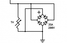
From the central system star ground you might connect to the chassis via something like the attached picture. The bridge is just one of the cheap kind.
From a comment AndrewT made in another thread, the purple wire from the transformers should connect to the chassis directly right at the transformer. Extending the lead reduces the shield's rf blocking capability.
From the central system star ground you might connect to the chassis via something like the attached picture. The bridge is just one of the cheap kind.
Attachments
Yes, I left the output ground off my drawing. That's one of the things that is confusing me.
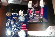
On the right side of the photo is the ground near the input section on the schematic marked G2 on the schematic, the left is of the ground near the output section, marked G1 on the schematic. Also there is a 0V TP solder point that I'm not sure of, on the left side of the photo, which I think is a third ground marked G2 on the schematic. I would say that OS intended for them to hit the star separately but I'm not sure as two are marked G2.
Note that I have v2.2 boards, I know there were many changes in v2.3 that may have clarified this.
(Just for clarity, the boards are temporarily attached to the sinks without standoffs, and the diodes aren't insulated yet)
Attachments
Last edited:
Just look at the traces, you see a star at the 0V/TP. The board is laid out to be it's own star ground and the GND connector near it is where you should connect it to the system star ground. R4 and the diodes near it serve to separate the potentially noisy power ground and the audio ground.
I have not studied the complex drawing.......... I have the wiring diagram complete. All grounds go to a single chassis connection, ..................!
I looked first at the inputs.
I see a red wire, presumably Signal Hot, going to the PCB.
I see the Signal Return/Ground going off in a different direction.
This leaves a loop in your input circuit that will pick up interference.
You MUST minimise the loops in EVERY circuit.
If the rest of the layout has loops like this first, then you have a disaster in the making.
The first priority is to close couple ALL Flow and Return Pairs.
Then connect any circuits that need a common reference.
That common reference is usually the "ground" reference that I call the Main Audio Ground (MAG).
That MAG does not need any connection to Chassis nor to Mains for good/exemplary Audio Performance.
The ONLY reason you need to connect MAG to Safety Earth is to comply with the safety requirement: All external/exposed conductive parts must be connected to Safety Earth/Chassis for any ClassI equipment. Other Classes of equipment have very different safety requirements.
Terry
Don't be put off. Like you I have limited electronics knowledge and also just wanted to build a nice sounding, "big balls" amp without having to experiment to get a good result. Component choice was mostly governed by recommendations in the build guide, availability here in the UK and component cost (never the cheapest). Maybe I got lucky, but I suspect not; it's just a good /excellent design which is likely to work very well with some components and even better with others. And btw i used the "crude" luxman way and it works just fine.
Don't be put off. Like you I have limited electronics knowledge and also just wanted to build a nice sounding, "big balls" amp without having to experiment to get a good result. Component choice was mostly governed by recommendations in the build guide, availability here in the UK and component cost (never the cheapest). Maybe I got lucky, but I suspect not; it's just a good /excellent design which is likely to work very well with some components and even better with others. And btw i used the "crude" luxman way and it works just fine.
- Home
- Amplifiers
- Solid State
- diyAB Amp The "Honey Badger" build thread