Any idea of when the next version (V2.3?) will be available? I noticed the V2.2 boards are in stock. Will the store wait until all of the V2.2 boards are gone before they make available the newer version? what is no one buys the V2.2 board because they're waiting for the newer version?
OS said a few pages back that the v2.3 changes are only convenience changes- larger holes, etc.
Right. Ostripper detailed the changes in post #391 and #396. Then in #402 clarified that these are minor changes to make construction easier. The schematic hasn't changed. I built the V2.2 and love it.

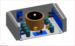
If anyone would care to comment regarding the major component placements within
the enclosure, I would appreciate that. Just a little worried there may be some interference issues I have overlooked. Using the amp, sp and ss boards, ps will be point to point.
the enclosure, I would appreciate that. Just a little worried there may be some interference issues I have overlooked. Using the amp, sp and ss boards, ps will be point to point.
Attachments
Another thought on board changes, perhaps too late but oh well. Would be nice to have solder pads on the top for Q16-21, and even 14 & 15. That way we could temporarily bolt the transistors to the heat sink, lay the board on top and align, and solder in place. Then remove, apply the mica and grease and do a final install.
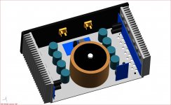
If anyone would care to comment regarding the major component placements within
the enclosure, I would appreciate that. Just a little worried there may be some interference issues I have overlooked. Using the amp, sp and ss boards, ps will be point to point.
Either way looks good to me. Look up nissman's or jo jo's amp (the other builds) or even builds in general on the solid state forum -
The build thread ....
http://www.diyaudio.com/forums/solid-state/96192-post-your-solid-state-pics-here.html
Lots of wisdom and idea's there....
")
OS
Another thought on board changes, perhaps too late but oh well. Would be nice to have solder pads on the top for Q16-21, and even 14 & 15. That way we could temporarily bolt the transistors to the heat sink, lay the board on top and align, and solder in place. Then remove, apply the mica and grease and do a final install.
The V2.4 I posted for everybody has all those changes. I have V2.3 boards , I didn't even know they were selling V2.2.
V2.2 was the original submitted to variac , I left for awhile - I saw that the boards (including the one's DIYA gave me) were V2.3 .
ALL the versions are electrically perfect with no errors , match the BOM , and just have slight mechanical variations. V2.4 ,( if they make them) ... Is perfect , but the other versions can be made just as perfect with a little careful tweaking.
OS
Oh absolutely! I'm very happy with the v2.2 boards. I was chomping at the bit to get going on this amp and bought the first boards available, which are totally functional and workable. Please don't take any of this as anything but constructive feedback. I've built a wall-wart powered DAC and an Aikido, this is my first foray into high power. Yet I feel confident, with the v2.2 boards and also the soft start, speaker protection, and upcoming PSU boards. You all have done an incredible job putting this together. No complaints, just trying to give back to the community with suggestions for improvement.
I'd buy even the v2.2 boards again in a heartbeat.
I'd buy even the v2.2 boards again in a heartbeat.
Reviewed version of the Honey Badger amp.
I have had a PM asking me to tell what transistors and settings I used for the Honeybadger amp used in the stereonet review so thought I would post here so others can see as well. I will copy and paste from the original options.txt file ostripper produced.
The cascode (Q3-4) can be setup in 2 (or more) ways.
- The first is a zener referenced design - omit R18 , replace
with a 1/2w- 1w 12-15V zener diode and set jumper pad "C" to "Z" with thin wire. The "CRZ" jumper pads
are located above D1-2 near "OFFSET". You will have a cascode reference of either 12 or 15V , depending
on Zener diode choice.
The VAS , (Voltage Amplification stage) is what takes the small signal from the cascode/current mirrors and creates a
wide, rail to rail "swing" . With 60V supplies ,this can be a large as 110V peak to peak. This signal is also what you "hear"...
after the big devices of the output stage increase the current a 1000 times or more.
The "OPTIONS" here are numerous. The small CCS just has a 20 turn 200R trimmer(R7) , this CCS controls the LTP current , it can
be adjusted between 1.8ma to almost 6ma , optimum is 70-100R-R7 giving 3.5ma at the "tail" of the LTP.
The "BIG CCS" is a part of the VAS .... with R27=68R ,the VAS will have a current of about 9 mA. Other values-R27 are 100R=6ma(I used R27=100r) or
56R=10.5ma. These changes will affect the Bias of the amplifier , MAKE SURE "bias"-R30 is set at maximum 500R if you change R27!
The VAS itself has 2 compensation modes:
1. Conventional miller compensation (CMC)- Omit R24 - (the feedback 820R 1/4w resistor) , omit EITHER C7 or C8 replace one witha wire jumper and the remaining one with a 68pF 300-500v silver mica capacitor . So ... C8= jumper R24=nothing C7=68pF(as an example).
Don't install an LC capacitor(this made it sound worse).
Q13 was 2SC3953
Q14/15 are MJE15032/MJE15033
Transformer is 600w 40-0-40V
I used a single transformer supplying 2 separate power supplys, one for each channel. Each supply had 4 x 12000uf 63v Elna for audio caps and some 100nf bypass caps.
Most important for the great sonic character of this amp was to change the imput capacitor "C1". I used in mine a Clarity Cap SA 4.7uf.
Regards
Simon
thank you very much Simon for sharing your Honeyabadger setup
No problem naf.
Most important for the great sonic character of this amp was to change the imput capacitor "C1". I used in mine a Clarity Cap SA 4.7uf.
Regards
Simon
Have you tried no cap at all? The DC offset can be completely zerod, so if your input has no DC then do you even need this cap?
Have you tried no cap at all? The DC offset can be completely zerod, so if your input has no DC then do you even need this cap?
Have not done this. I wouldn't really do that unless there was extra circuitry (dc servo) there anyway.
This thing has had enough experimenting by me since building it. Am happy with the results.
Simon
Thanks for posting your settings Simon. Last question: which output devices did you use?
NJW0281 / NJW0302
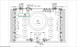
If someone wouldn't mind explaining to a layman the principles behind a star ground, or if indeed that is what is supposed to happen in this context. The major ground contact is intended to be attached to the case floor. Are all the the other various contacts supposed to be routed to the same point, or can a floor attachment be made at any convenient fllor point?
Attachments
- Home
- Amplifiers
- Solid State
- diyAB Amp The "Honey Badger" build thread