Community input
I've identified from the forum some minor issues with layout.
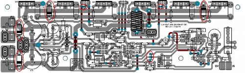
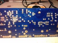
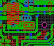
Outlined in red circles below - (first pix)
#1 - D4-5 (D8-9) - output snubber diodes. Read that the fit is tight ...Badger holes are 1mm
I checked MR856G http://www.onsemi.com/pub_link/Collateral/MR850-D.PDF ...
1.3mm diameter ... oops.
#2 - "CRZ" jumper is masked.
#3 - C18-19 pads are masked.
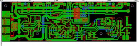
#4 - jumperless design. The print side of the board shows jumpers , but these are actually plated through holes and run on the back layer (physically it is jumperless) ...easy fix ! I would however suggest real jumpers for the V+ trace as the plated through holes might be a current "bottleneck"(V2.2). A more permanent solution would be to increase the number of holes on the 2 points where the V+ trace crosses other traces. Sort of like the power and ground planes on a computer motherboard.
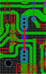
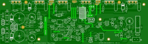
An example is below (pix 2).
These "bugs" are very minor and the version 2.3 board works and is even reviewed (no effect on proper operation). Just cosmetic and ease of construction updates.
Any other version 2.4 suggestions are welcome !!
OS
I've identified from the forum some minor issues with layout.
Outlined in red circles below - (first pix)
#1 - D4-5 (D8-9) - output snubber diodes. Read that the fit is tight ...Badger holes are 1mm
I checked MR856G http://www.onsemi.com/pub_link/Collateral/MR850-D.PDF ...
1.3mm diameter ... oops.
#2 - "CRZ" jumper is masked.
#3 - C18-19 pads are masked.
#4 - jumperless design. The print side of the board shows jumpers , but these are actually plated through holes and run on the back layer (physically it is jumperless) ...easy fix ! I would however suggest real jumpers for the V+ trace as the plated through holes might be a current "bottleneck"(V2.2). A more permanent solution would be to increase the number of holes on the 2 points where the V+ trace crosses other traces. Sort of like the power and ground planes on a computer motherboard.
An example is below (pix 2).
These "bugs" are very minor and the version 2.3 board works and is even reviewed (no effect on proper operation). Just cosmetic and ease of construction updates.
Any other version 2.4 suggestions are welcome !!
OS
Attachments
While on the subject of the AB amp bom, may I be allowed to take the discussion a couple of rungs further down the electronic evolutionary ladder. I noticed that the digikey address for R23 and R27 brings up 1/4 watt while the bom is calling for 1/2 watt. Is that an oversight or is it a non issue. Remember you are dealing with a strictly plug and play guy here.
While on the subject of the AB amp bom, may I be allowed to take the discussion a couple of rungs further down the electronic evolutionary ladder. I noticed that the digikey address for R23 and R27 brings up 1/4 watt while the bom is calling for 1/2 watt. Is that an oversight or is it a non issue. Remember you are dealing with a strictly plug and play guy here.
At rest , the VAS ( derived from P = E squared/R) = pulls just .005 watt through R23-27. Most OEM's (commercial amps) use 1/4w to 1/2w - overkill !! If the drivers (Q14-15)are loaded these resistors might see a little more. 1/4w will do !
I specified 1/4 watt for almost the whole Badger's small resistors as they are most common (radio shack - e waste), but 1/8w will do for most. I will refine the BOM with more choices. 1/8 watt devices might even look/fit better on the small signal stages (LTP/mirror). 1/4 watt's fit but slightly cover the screen printing
 .
.R32-33 ,R36-50, and R53-54 are the only resistors that see .25w(1/4w) + ....
observe these ratings!!!
PS - R18/19 (the cascode divider ) sees .02w , most of the input stage LPT.mirror only .001 - .002w or less. We are QUITE derated !!
OS
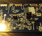
I'm finding the holes for Q10, 11 and 12 to be too small as well.
What version board (2.3?) I just fit a 2sc3503 , it's even loose !
In fact , the to-220 (slightly larger pins)even fits Q10-12 and Q13-15 .. all the medium sized transistor holes.
The only device that has a larger collector pin is the mje340/350 pair. For these ,I could use a sewing needle for the Q10 middle hole.
picture below shows everything.
OS
Attachments
Last edited:
What version board (2.3?) I just fit a 2sc3503 , it's even loose !
In fact , the to-220 (slightly larger pins)even fits Q10-12 and Q13-15 .. all the medium sized transistor holes.
The only device that has a larger collector pin is the mje340/350 pair. For these ,I could use a sewing needle for the Q10 middle hole.
picture below shows everything.
OS
V 2.2
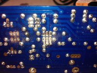
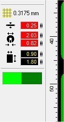
First pic shows Mouser PN 512-KSA1381ESTU inserted, with original board holes drilled out to 1.5 mm. (I don't have a "before" pic.)
Second pic shows in red what size the original holes were (though the solder plates were visible.) In blue it shows the size they needed to be to fit this component.
Second pic shows in red what size the original holes were (though the solder plates were visible.) In blue it shows the size they needed to be to fit this component.
Attachments
looks like the pitch (how far apart the holes are) might be the problem, but OS's fit just fine.. ?
Maybe we'll make these in red so people know that they're the latest. .
It would be nice to have a Digi-key BOM too at some point. I deal with them a lot. Not a big deal though
Athough if the BOM is in the right spreadsheet format the whole order just sliiiiiides in..
Although Mouser prob has the same thing?
Last edited:
wow 1.5mm !! That's big diode territory !
http://www.classiccmp.org/rtellason/transdata/ksa1381.pdf
States .75mm , I set the V2.2 to .82mm for all the to-126's (below 1). I do not know how this happened as I submitted the correct drilling size. I don't know how they got to V2.3 (the holes are right on these) , but (at least)on the V2.2 sprint file , it was right. STRANGE !!
Just about have V2.4 done (below 2). I'm using parts on hand,a V2.3 board, and datasheets to tweak the holes.
OS
Attachments
Yes , Mouser has the spreadsheet BOM conversion ... http://www.mouser.com/BOMHelp/
Variac , If you could give the mounting hole spacings and any other requests
(Maybe a real badger on the board) .
I'm doing this on the build thread as this is where the information is (builders -holes - spacings - problems?).
On the discussion thread - component options , smaller input stage resistors (1/8 watt) , fets !! I'll do that before the final BOM update - spreadsheet stage.
OS
Variac , If you could give the mounting hole spacings and any other requests
(Maybe a real badger on the board)
.I'm doing this on the build thread as this is where the information is (builders -holes - spacings - problems?).
On the discussion thread - component options , smaller input stage resistors (1/8 watt) , fets !! I'll do that before the final BOM update - spreadsheet stage.
OS
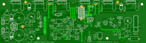
V2.4 is done.
PCB changes -
1. Zener based cascode reference is "locked in" and jumperless.
2. Gave most drillings another .1mm extra diameter.
3. Fixed DIYA universal mounting holes.
4. Fixed the few pads that were solder masked.
5. Removed jumper screenprints.
6. 3A diode holes at 1.75mm.
7. Increased current capacity of power rails (more through-holes - jumperless) .
General "housecleaning" and a more verbose BOM. This is the BOM that the
spreadsheet / mouser "one click" ordering system will be based on.
BOM changes -
1. All 4mm resistor placements are 1/8W devices (3mm - will see the screenprint).
2. 6mm = 1/4w , 8-10mm are 1/2w , power devices are the same.
3. Added notes and more choices for all semi's.
Below is the output ...
OS
Attachments
Last edited:
OK great!
So I understand that you've already fixed the holes?
I don't have any boards here unfortunately, we sent them all to the store.
Maybe you still have the boards I sent you?
Could you confirm the center to center distance apart of the upper holes
and distance apart of the lower holes, and the distance vertically between the uppers and lowers?
If I remember correctly Jason had to have a guy move the lower holes (the ones closer together) Was that your finding? Did any traces need moving?
So you used the UMS diagram in the store?
Sorry, I don't have a reference and it was quite a while ago. I have a message in to Jason, since he actually worked with the guy. So we can get some confirmation from him. The mounting holes are quite big too, but I don't know, maybe that's best..
So when I talk to Jason and you confirm the above we can send out the order!
Mark
some more suggestions . . .
HA! I made the mistake of adding jumpers on my first board, but noticed the jumpers were already built in before I made the second board.
The Honey Badger rocks, by the way.
I have some additional minor suggestions:
The image of a resistor inside of the inductor could be confusing to some builders, as R49 is already located outside the inductor.
Q9 is in the way of the nut or bolt holding Q10 to the heatsink.
The fuse holders I used were wider than the ones used in the prototype, and are in the way of R53 and R54.
Quick-Connects can be pretty tight, and it puts a lot of stress on the board when connecting and disconnecting. Some additional holes for PCB standoffs near the quick-connects would prevent the board from flexing so much, especially near "OUTPUT" as I can't fit my fingers under the board to support it.
Thank you so much for the work you have volunteered! I may build another one with the new boards!
Revise the build guide to state that the jumpers are already in place on the boards.
HA! I made the mistake of adding jumpers on my first board, but noticed the jumpers were already built in before I made the second board.
The Honey Badger rocks, by the way.
I have some additional minor suggestions:
The image of a resistor inside of the inductor could be confusing to some builders, as R49 is already located outside the inductor.
Q9 is in the way of the nut or bolt holding Q10 to the heatsink.
The fuse holders I used were wider than the ones used in the prototype, and are in the way of R53 and R54.
Quick-Connects can be pretty tight, and it puts a lot of stress on the board when connecting and disconnecting. Some additional holes for PCB standoffs near the quick-connects would prevent the board from flexing so much, especially near "OUTPUT" as I can't fit my fingers under the board to support it.
Thank you so much for the work you have volunteered! I may build another one with the new boards!
I used the PDF that went with the badger boards , post a link if there is a "UMS" PDF .OK great!
So I understand that you've already fixed the holes?
I don't have any boards here unfortunately, we sent them all to the store.
Maybe you still have the boards I sent you?
Could you confirm the center to center distance apart of the upper holes
and distance apart of the lower holes, and the distance vertically between the uppers and lowers?
If I remember correctly Jason had to have a guy move the lower holes (the ones closer together) Was that your finding? Did any traces need moving?
So you used the UMS diagram in the store?
Sorry, I don't have a reference and it was quite a while ago. I have a message in to Jason, since he actually worked with the guy. So we can get some confirmation from him. The mounting holes are quite big too, but I don't know, maybe that's best..
So when I talk to Jason and you confirm the above we can send out the order!
Mark
I did move the V+ rail trace (and others) to get more clearance for the bottom holes.
1. Upper (to) lower holes = 60mm (76 - 60 /2 = 8mm from top/bottom)
2 . top holes = 240mm centered (253 -240 /2 = 6.5mm from L/R )
3. bottom holes= 120mm centered (253 - 120 /2 = 66.5mm from L/R)
Holes are 5mm - what do you want ?
Your Email "hates" my Email (I am tagged as a spammer- mailer deamon), if I could just post the sprint stuff here would make it easy. (I have to make a whole new email account - most likely Gmail).
This is good - input !
by ByronInLawrence -I have some additional minor suggestions:
1. The image of a resistor inside of the inductor could be confusing to some builders, as R49 is already located outside the inductor.
2. Q9 is in the way of the nut or bolt holding Q10 to the heatsink.
The fuse holders I used were wider than the ones used in the prototype, and are in the way of R53 and R54.
3. Quick-Connects can be pretty tight, and it puts a lot of stress on the board when connecting and disconnecting. Some additional holes for PCB standoffs near the quick-connects would prevent the board from flexing so much, especially near "OUTPUT" as I can't fit my fingers under the board to support it.
#1-That would require redrawing the Macro (alexmm's macro) ...easy !!
#2- looked and thought this out .... Q9 forms the high gain pair with Q10 -best kept very close to Q10. With a little lead magic one can mount Q9 much lower than Q10 , the Q10 bolt on mine is 3-4mm above the top of Q9. Mount Q10-12 as high as they will go. (datasheet says 20mm+ without clipping the leads).
#3- You want MORE holes !
If Variac approves (example below).Chunek - It will be good if all transistors' pads openning on top and bottom. Easy for users to align or adjust height and pre-solder while mount on heatsink.
I looked at my boards - I will add them (double sided pads - non masked) .
OS
Attachments
Last edited:
To avoid confusion on my part, I take it when using the rev 2.3 board the only external jumper required would be the c to z for the zener application?
Yes , also I noticed the pads are masked.(scratch off)C-Z will reference to cascode divider to ground... period. C-R will also work , this will reference the zener to the virtual "near" ground (-.7v) of the css. C-Z and C- R model almost identical , I have seen both techniques used in popular amps. Maybe , I should consider replacing the C-R-Z as there might be very minor sonic differences between the settings.
I will try each myself... They model nearly identical (same PSRR - THD).
(go for C-Z) I think nissman's is set like that.
OS
I'm thinking my next project will be a liquid-cooled home theater amp with 5 Honey Badger boards...
That's a lot of "juice" - best left for the Canadian Hydropower
 .
.HTPC - If I did a 4.1 or 5.1 , I'd mix 3 badgers with 2-3 lm3886 IC amps.
Example - 4.1 = 2 badger's - 2 LM3886's , separate HD "bassbadger".
Rear channels are typically closer , only L-R/R-L audio information .. A badger would be overkill.
My 2.1 setup will have a few inches of space left in the case - enough for the chips.
OS
Last edited:
- Home
- Amplifiers
- Solid State
- diyAB Amp The "Honey Badger" build thread