300VA Power supply, Honey Badger Monobloc or Dualmono
This is convenient to do with monobloc/dualmono.
For Honey Badger, it is about 35+35vac 300va.
Then there's the matter of selecting a power supply that could be charged up full when the amplifier is pushing a 4 ohm speaker at the limits of the transformer, such as about 180 watts with our 300va transformer. There's no extra clearance for charging the supply. Adding a lot more capacitance, increases the load, delays the charge-up, and cuts both clarity and transient/dynamic power.
So, instead of that, we need something smaller, faster, and easily charged, to match that 300va transformer.
And what power supply recovers fast enough to get full, a split second after a bass beat, despite a maxed out 300va transformer? No problem. See attachment.
That's just transformer selection--choose enough voltage for the 8 ohm application, and insufficient current for output transistor/fuse breakage when 4 ohm speakers are connected.Are you able to build an amp where you can choose to send 4, 6, or 8 to your speakers?
This is convenient to do with monobloc/dualmono.
For Honey Badger, it is about 35+35vac 300va.
Then there's the matter of selecting a power supply that could be charged up full when the amplifier is pushing a 4 ohm speaker at the limits of the transformer, such as about 180 watts with our 300va transformer. There's no extra clearance for charging the supply. Adding a lot more capacitance, increases the load, delays the charge-up, and cuts both clarity and transient/dynamic power.
So, instead of that, we need something smaller, faster, and easily charged, to match that 300va transformer.
And what power supply recovers fast enough to get full, a split second after a bass beat, despite a maxed out 300va transformer? No problem. See attachment.
Attachments
The Universal boards as chugging along. This time we wanted something REALLY universal and really good! Trouble is we were putting in so many features that they just don't all fit! So we've regrouped a bit and are now working on the final format. There's no doubt we'll stick with this one once we get the mounting holes to fit!
Last edited:
Universal PSU
Thanks but that really doesn't help me or other members who have been chasing availability of these boards for some time now.... I, for one really need to know when. "some time in the future" just doesn't cut it for me. Also, I (and I suspect many other people) have already ordered components to fit the current design and are just waiting for boards - so a design change potentially really throws a stick in the spokes....
So first of all - please provide an estimate for having either the new design or re-run of the current design available. I need to decide whether I make my own boards - something I'd prefer not to do...
Sorry to sound grumpy but i'm tired of not knowing how to proceed.
thanks
The Universal boards as chugging along. This time we wanted something REALLY universal and really good! Trouble is we were putting in so many features that they just don't all fit! So we've regrouped a bit and are now working on the final format. There's no doubt we'll stick with this one once we get the mounting holes to fit!
Thanks but that really doesn't help me or other members who have been chasing availability of these boards for some time now....
I, for one really need to know when. "some time in the future" just doesn't cut it for me. Also, I (and I suspect many other people) have already ordered components to fit the current design and are just waiting for boards - so a design change potentially really throws a stick in the spokes....So first of all - please provide an estimate for having either the new design or re-run of the current design available. I need to decide whether I make my own boards - something I'd prefer not to do...
Sorry to sound grumpy but i'm tired of not knowing how to proceed.
thanks
Last edited by a moderator:
I've recently received my boards, very nice quality but can confirm that the CRZ jumpers and C18/C19 solder pads are lacquered over as supplied.
My build time will almost certainly be the slowest in history but then again I like to enjoy the process as much as the finished result.
For any other UK builders, which supplier did you use for the 0.22R 5 watt resistors? Are the ordinary green ceramic cased wire wound ones OK?
My build time will almost certainly be the slowest in history but then again I like to enjoy the process as much as the finished result.
For any other UK builders, which supplier did you use for the 0.22R 5 watt resistors? Are the ordinary green ceramic cased wire wound ones OK?
Hi BKevin,
The PS I diy it based on universal ps. Running fine since last Nov
I only use 20kuf per rail. On board cap c13,17 using 400v 47uf and c1,10 using 250v 2.2uf to have faster response of bass. As for input cap find that 1.53uf (ie 4.7uf + (2.2uf//0.082uf)) has best response to my ear. Just my personal preferences.
James
The PS I diy it based on universal ps. Running fine since last Nov
An externally hosted image should be here but it was not working when we last tested it.
An externally hosted image should be here but it was not working when we last tested it.
An externally hosted image should be here but it was not working when we last tested it.
An externally hosted image should be here but it was not working when we last tested it.
I only use 20kuf per rail. On board cap c13,17 using 400v 47uf and c1,10 using 250v 2.2uf to have faster response of bass. As for input cap find that 1.53uf (ie 4.7uf + (2.2uf//0.082uf)) has best response to my ear. Just my personal preferences.
James
Last edited:
You've got more options. One way to clear up the blurry bass is using a small size input cap. The other way is to first change both C3 and C4 to identical models of 220uF Panasonic FC. SO, in your case with 1.53uF input cap, you could then use 3.3uF input cap.As for input cap find that 1.53uf (ie 4.7uf + (2.2uf//0.082uf)) has best response to my ear. Just my personal preferences.
Bigger input cap = warmer/distortion
Smaller input cap = clearer/colder and less low pitches
Smaller NFB-shunt cap = warmer/distortion
Bigger NFB-shunt cap = clearer/colder and better quality lowest pitches
*The above adjusts bass harmonic balance, but if you want to adjust bass roll off then:
Bigger input cap+Bigger NFB-shunt cap = deeper
There's no wrong answer, but I think you should fine tune this to best fit your speakers and preferences.
The Honey Badger schematic shows 220.1uF series to 820R which is for maximum impact big loud boom suited to outdoor PA; However, for indoor or general purpose use, I suggest 440uF for clearer low pitches.
Last edited:
Re : Universal PSU
Hi bkevin,
I am also not using PSU board.
I directly connect the decoupling cap, bridge diode and transformer by using AWG 14 wire. Cap is tied to the transformer with cable tie and diode is secured to the chasis.
By changing the current density ratio between ground and power rail to cap, you can also adjust the tonal balance of the sound. If all wire is AWG 14 solid wire, sound is very clean. If reducing the current density of power rail to AWG 16, sound is more vibrant although not that well focused.
With the default PSU board, you lost that option for tuning capability. The board layout already defines the current ratio between power and ground.
Just my experience.
Regards,
Lou
Thanks but that really doesn't help me or other members who have been chasing availability of these boards for some time now....
So first of all - please provide an estimate for having either the new design or re-run of the current design available. I need to decide whether I make my own boards - something I'd prefer not to do...
Sorry to sound grumpy but i'm tired of not knowing how to proceed.
thanks
Hi bkevin,
I am also not using PSU board.
I directly connect the decoupling cap, bridge diode and transformer by using AWG 14 wire. Cap is tied to the transformer with cable tie and diode is secured to the chasis.
By changing the current density ratio between ground and power rail to cap, you can also adjust the tonal balance of the sound. If all wire is AWG 14 solid wire, sound is very clean. If reducing the current density of power rail to AWG 16, sound is more vibrant although not that well focused.
With the default PSU board, you lost that option for tuning capability. The board layout already defines the current ratio between power and ground.
Just my experience.
Regards,
Lou
We got lots of suggestions and demands on how we could greatly improve the PSU boards. Many of them were quite useful so we felt we needed to incorporate them, but it isn't easy because we're also trying to make them fit better in our chassis' where some new mounting points have been added so they're more versatile. Unfortunately it's a design process so unpredictable for both the boards and the chassis'. So far it's been really difficult and slow. We've had some recent breakthroughs, so we're optimistic, but don't think they'll be in the store for 2 months.
The new boards will accommodate bigger caps, but I can't think of any way that they wouldn't work just fine with any components that worked with the old boards.
The new boards will accommodate bigger caps, but I can't think of any way that they wouldn't work just fine with any components that worked with the old boards.
Thanks but that really doesn't help me or other members who have been chasing availability of these boards for some time now....
So first of all - please provide an estimate for having either the new design or re-run of the current design available. I need to decide whether I make my own boards - something I'd prefer not to do...
Sorry to sound grumpy but i'm tired of not knowing how to proceed.
thanks
Hi Daniel,
Thanks for your recommendation and will look into the NFB shunt cap for next mod! The original combination of 4.7uf input cap and 220uf NFB shunt cap, the bass is muddy and no layering on my speakers. Reducing the input cap, the details of the bass start to coming out but it is still too draggy for my taste. The roll off frequency is still around 1Hz plus with 1.53uf.
By reducing on board cap from 470uf + 100uf to 47uf + 2.2uf, the bass start to clock right to my speakers. It came out note by note with good layering and not disturb other instruments when all instruments come into play. This may possible due to increasing the charge and discharge rate of cap with smaller cap. (To increase the charge capacity I use high voltage rating 400V 47uf cap) This is purely my own preference.
I enjoy Honey Badger even with the original setting.
James
Bigger input cap = warmer/distortion
Smaller input cap = clearer/colder and less low pitches
Smaller NFB-shunt cap = warmer/distortion
Bigger NFB-shunt cap = clearer/colder and better quality lowest pitches
*The above adjusts bass harmonic balance, but if you want to adjust bass roll off then:
Bigger input cap+Bigger NFB-shunt cap = deeper
for indoor or general purpose use, I suggest 440uF for clearer low pitches.
Last edited:
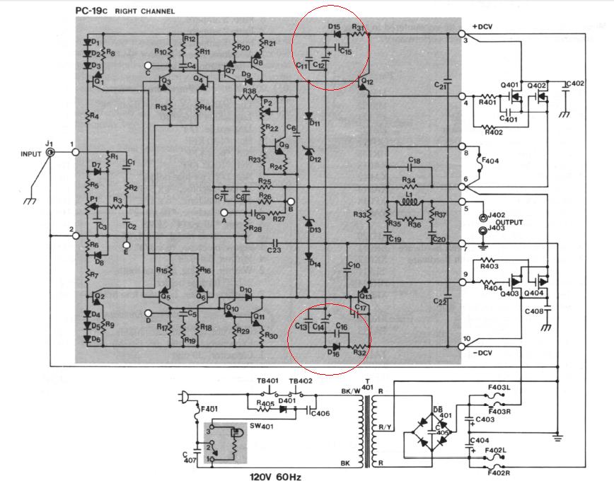
Oh, thanks for the info! 2u2 for C11, C15?
I see that R32, probably need to be changed from resistors to diode drops (or diode series to resistor) to give consistent performance.
So, it would be fairly orthodox to use 100u for C11, C15, but actually needing 2u2 indicates that "something else" is going on, such as the schematic's power decoupling for predrive section, has not fully worked for high speed transients. Power board umbilical cable, chassis layout and transformer voltage could foobar resistors somewhat, so we probably need something more than mild suggestion of current drop--it needs an assured voltage drop with regulators, or with diodes like the Hafler DH-220. The diodes could make C11, C15 work as expected so that the 220u (or 100u) work properly and without hindrance from all of the other power caps in the system.
If your little cap is also the most efficient cap, that option works too.
Other possibility:
Your 220u didn't like the 100n guesswork/shotgun bypass at all? That could happen and would be ringing (and arbitrarily non-specific bypass ringing in the power circuit is rather destructive to predrive audio quality). It is possible to replace the 100n with a 0.47u bipolar electrolytic to resolve that problem. Would look crazy and be hard to explain, but tiny bipolar electrolytic just blend easier with big caps, with much less chance of ringing. Try Nichicon ES for the little one.
The two possibilities are:
The simple version of the circuit just wasn't effective enough, Or
A certain model of 220u set up ringing conflict with a certain model of 100n
Last edited:
Thanks everyone!
Now that I know we're looking at 2 months+ for the PSU PCB's (thx variac for finally putting me and I'm sure many others out of my misery on that score) I'll look at other options, and "wiring together" a psu seems to be eminently achievable (Thx Lou & James for sharing your experience).
Lou, just so I understand - you said "If reducing the current density of power rail to AWG 16" - I guess you meant to say "if increasing current density"? [smaller conductor = higher current density]? I'm hoping i understood you - but not so sure now.
thx
Thanks everyone!
Now that I know we're looking at 2 months+ for the PSU PCB's (thx variac for finally putting me and I'm sure many others out of my misery on that score) I'll look at other options, and "wiring together" a psu seems to be eminently achievable (Thx Lou & James for sharing your experience).
Lou, just so I understand - you said "If reducing the current density of power rail to AWG 16" - I guess you meant to say "if increasing current density"? [smaller conductor = higher current density]? I'm hoping i understood you - but not so sure now.
thx
Hi bkevin,
Let us just use the word of current capability. Current density is the wrong word that I used before.
AWG 16 has a diameter of 0.0508 inch while AWG 14 has a diameter of 0.0641
So AWG 16 (thinner) is capable to carry less current than AWG 14.
And solid wire has more current capability than multi strain wire
There is also a rule of thumb that ground wire should be at least 4X of the current capability than the corresponding signal wire
Ground plane is supposed to be a perfect conductor. Relatively speaking. And 4X is a good starting point.
Lou
By changing the current density ratio between ground and power rail to cap, you can also adjust the tonal balance of the sound. If all wire is AWG 14 solid wire, sound is very clean. If reducing the current density of power rail to AWG 16, sound is more vibrant although not that well focused.
With the default PSU board, you lost that option for tuning capability. The board layout already defines the current ratio between power and ground.
Just my experience.
By reducing on board cap from 470uf + 100uf to 47uf + 2.2uf, the bass start to clock right to my speakers. It came out note by note with good layering and not disturb other instruments when all instruments come into play. This may possible due to increasing the charge and discharge rate of cap with smaller cap. (To increase the charge capacity I use high voltage rating 400V 47uf cap) This is purely my own preference.
Thank you Andrew for the voice of reason.
Why are posts like the ones quoted left mainly unchallenged?
How many newcomers/amateurs get pulled in by this?
Also looking at Daniel here, who has been warned not long time ago.
At least the above quotes have 'personal preference/experience' disclaimers.
If your little cap is also the most efficient cap, that option works too.
Other possibility:
Your 220u didn't like the 100n guesswork/shotgun bypass at all
The two possibilities are:
The simple version of the circuit just wasn't effective enough, Or
A certain model of 220u set up ringing conflict with a certain model of 100n
Hi Daniel,
Possible my 220uf didn't work well with 100n.
The current one, I am using Phillips 250V 2.2uf. For normal listening, I just turn on 5% volume, at most 20% ONLY. It is working fine. So far it didn't go beyond that. As what you said, I am worried also as this little cap may not be able to support full volume. I will try it this weekend.
James
Last edited:
Daniel is beyond help.Thank you Andrew for the voice of reason.
Why are posts like the ones quoted left mainly unchallenged?
How many newcomers/amateurs get pulled in by this?
Also looking at Daniel here, who has been warned not long time ago.
At least the above quotes have 'personal preference/experience' disclaimers.
His non standard use of english has me regularly confused.
Just recently he actually posted a few sentences that I could understand and surprisingly I had to agree with what he described.
But the vast majority of Daniel's posts are either completely unfathomable or just plain wrong where I can put some meaning to his gobbledegook.
For getting relatively normal capacitor values to work, here's a couple of possible solutions:Possible my 220uf didn't work well with 100n.
*A fairly orthodox approach, with capacitance value very close to Ostripper's specs, but with a more seamless method of bypassing, is to make C10, C11, C14, C15, all identical models of rather decent 100uF capacitor. This idea makes high efficiency 200uF per rail.
Or,
*If you want to set minimized capacitance value for that area, you could make C10, C11, C14, C15, all identical models of rather decent 47uF capacitor. The resulting value of approximately 100uF per rail is still relatively normal at small signal locale. However, smaller than this might begin to look weird, which could possibly indicate the problem you're looking for may be elsewhere.
P.S.
I did post a rather quick reacting power supply design up at post#265. Although faster might be helpful, power supply isn't an ideal location to attempt small signal support; so, it really can't substitute for a more idealistic small signal power circuit like either Hafler's diodes or regulators at amplifier front end. In my opinion, if we were actually looking for the right spot to fix, then we might want to remedy the omissions at Honey Badger's R32, R33, but I don't know if Hafler's diodes or regulators for amplifier front end, are compatible or not.
Last edited:
I did post a rather quick reacting power supply design up at post#265. Although faster might be helpful, power supply isn't an ideal location to attempt small signal support.
Hi Daniel,
Thanks for your recommendation! I wish I have the space to install this fast reacting power supply but it is limited.
Last few days, I did some high volume test with c11, c15 of 2.2uf caps, the 4 ohm speakers started to sound like not feed well when volume > 50%. I had 4 pcs of Nichicon muse 47uf caps on hand. After changing that, it came back to normal. Now enjoying the music and happy with this setup.
The only remaining parts for finetuning are the NFB cap + current mirror trans KSA1015.
Thanks,
James
- Home
- Amplifiers
- Solid State
- diyAB Amp The "Honey Badger" build thread