2sc1845 / F /P
Same goes for the NPN small signal. Q1/2 should be the Fxx. 3/4 -7/8 can be F or P (p is cheaper - .06c USD).
Mouser has many of each !! We won't run out (60,000+)
The "P" is discontinued and is sale priced.
For least offset ,do a basic B-E test on Q1/2 with the diode mode on a DMM.
Match within 5 on the last digit (example 711 -715 on DMM .. B-E). This will allow for near
0 offset with only 1/8 - 1/4 turn on R17 (DC offset).
OS
Same goes for the NPN small signal. Q1/2 should be the Fxx. 3/4 -7/8 can be F or P (p is cheaper
- .06c USD).Mouser has many of each !! We won't run out (60,000+)
The "P" is discontinued and is sale priced.
For least offset ,do a basic B-E test on Q1/2 with the diode mode on a DMM.
Match within 5 on the last digit (example 711 -715 on DMM .. B-E). This will allow for near
0 offset with only 1/8 - 1/4 turn on R17 (DC offset).
OS
Last edited:
The answer would be in amperes.Question:
For a Honey Badger monobloc with 3xMJL3281, 3XMJL1302, and a load of 2.6DCR, then what what is the maximum transformer (in amperes) that will safety throttle before the outputs could be harmed? Specifically, I'm looking for the "maximized power" figure, such as 45+45vac in case of 8 ohm speakers, but need an answer in amperes to hold back the power in the case of 4 ohm speakers so that output device SOA cannot be exceeded. Assume worst case, music production use (digital organ, 32' stop, young caffeinated organist). How many amperes transformer is safe in these conditions?
Replacing the fuses each time the organist touches a bass pedal would be unsuccessful in a music production environment. If either fuses or outputs blow, the concert is ruined. Same question, different language: Given a monobloc with 45+45vac transformer and a 4 ohm speaker, what amperage transformer can protect the fuses via transformer throttling?Dan -The fuses "throttle" the outputs.
This is the same question: What amperage transformer can protect the concert via transformer throttling?
On fuses....
For a electronic organ (instrument amp) ,A Slo-blow fuse is often used.
They also fuse the speakers (audiophiles hate this).
EDIT - they also use breakers ...
For the 100ms SOA of the Badger outputs, a fast blow is used. Coincidentally, these fuses have the same .1 second T as the outputs SOA. If this fuse was 7 amps (I use this for my 4 OP device badger -"the prototype") , then it would pass 14 amps for 100ms. This point depends on the I2T of the fuse (time to melt) .
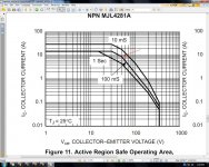
If one did use a Badger for extended Synth/Organ usage , just a small increase in fuse rating (fast blow- 8A)along with lower rail voltages 40-0-40Vac would make for an OP with 24A @100ms SOA (see chart below -mjl4281) and for 35-0-35vac trafo the 100ms SOA would be 30A! Of course , the fuses would blow at [rating X 2 - I2T] .... 16a , therefore saving the outputs.
For your EXACT question: This is what the OEM's do ! They use an "anemic" trafo that will cause the rails to drop to a lower voltage, therefore entering into a better region of the SOA (below - red arrow/ 50Vdc). An Antec 300VA at 45Vac will "sag" to 38-40vac at 10A (an estimate-based on antek's PDF). At this point you might blow the 7A or 8A fuse as well.
My final recommendation for a Badger "swiss army knife" would be the Antek as-3440 or as-4440 http://www.antekinc.com/pdf/AS-4440.pdf + the MJL outputs.
1 per channel- dual mono... they are only 5.25" -4440 and 5" -3440
They also have dual 15vac secondaries for your DAC/other small signal "addons".
I would love to know what conditions could take this amp out if it is constructed in this way. (redundant safety considerations)
OS
For a electronic organ (instrument amp) ,A Slo-blow fuse is often used.
They also fuse the speakers (audiophiles hate this).
EDIT - they also use breakers ...
For the 100ms SOA of the Badger outputs, a fast blow is used. Coincidentally, these fuses have the same .1 second T as the outputs SOA. If this fuse was 7 amps (I use this for my 4 OP device badger -"the prototype") , then it would pass 14 amps for 100ms. This point depends on the I2T of the fuse (time to melt) .
If one did use a Badger for extended Synth/Organ usage , just a small increase in fuse rating (fast blow- 8A)along with lower rail voltages 40-0-40Vac would make for an OP with 24A @100ms SOA (see chart below -mjl4281) and for 35-0-35vac trafo the 100ms SOA would be 30A! Of course , the fuses would blow at [rating X 2 - I2T] .... 16a , therefore saving the outputs.
For your EXACT question: This is what the OEM's do ! They use an "anemic" trafo that will cause the rails to drop to a lower voltage, therefore entering into a better region of the SOA (below - red arrow/ 50Vdc). An Antec 300VA at 45Vac will "sag" to 38-40vac at 10A (an estimate-based on antek's PDF). At this point you might blow the 7A or 8A fuse as well.
My final recommendation for a Badger "swiss army knife" would be the Antek as-3440 or as-4440 http://www.antekinc.com/pdf/AS-4440.pdf + the MJL outputs.
1 per channel- dual mono... they are only 5.25" -4440 and 5" -3440
They also have dual 15vac secondaries
for your DAC/other small signal "addons".I would love to know what conditions could take this amp out if it is constructed in this way. (redundant safety considerations)
OS
Attachments
Last edited:
Toroid: Electrostatic screen or GOSS band?
Hi
After looking at toroids for this project I have a couple of questions.
Does it need and electrostatic band?
or a GOSS band, I know it reduces stray fields but does it need it in this amp? Or does it depend on where I place the toroid?
Hi
After looking at toroids for this project I have a couple of questions.
Does it need and electrostatic band?
or a GOSS band, I know it reduces stray fields but does it need it in this amp? Or does it depend on where I place the toroid?
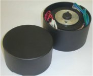
Not absolutely required (a band) ... but , why not ? (below) - http://www.antekinc.com/pdf/CA-xxx.pdf
These look real cool , as well.
OS
These look real cool , as well.
OS
Attachments
Any transformer I have not bought one yet...
I'm just about to put a couple of transformers into the swap meet. They're 500va, 3230v primary, with 2 x 40-0-40 secondaries. so you could use one for a stereo amp or go macho using the two of them for a pair of monoblocs. I've been using them in Naim NAP135 clones but I'm upgrading to HackerNAP amps (from pinkfishmedia forum) which is similar design but have split front end and output stages and runs at different voltages. Details and photolinks by the weekend
Tim
So, if I wanted to attempt protecting both the outputs and fuses?. . . and for 35-0-35vac trafo the 100ms SOA would be 30A! Of course , the fuses would blow at [rating X 2 - I2T] .... 16a, therefore saving the outputs.
http://www.antekinc.com/pdf/AN-4235.pdf
That's the transformer choice for nonstop service in rough conditions music production use?
And a weird alternative:
Automotive 15a? "Short Stop" automatic circuit breaker in parallel with high wattage 3 ohm power resistor, used as speaker jack protector. Well, that was the basic idea, but actually how much Short Stop device amperage and how much resistor ohms do I need to build an effective short protection device. . . that can stop a short but not stop a concert? I suppose with higher voltage transformer we'd need the 10a short stop?
So, if I wanted to attempt protecting both the outputs and fuses?
use a resetable magnetic circuit breaker instead..Tyco Electronics - Telecom OSP US ......fuses are meant to be replaced, they get broken instead of the traffo burning out....with output devices, blown fuses means shorted output devices, they get fried followed by the fuses IME....
PHOENIX CONTACT | Device circuit breakers
Referring to the Honey Badger schematic, I see it does have this dual voltage feature. Look at the top of the schematic.I've been using them in Naim NAP135 clones but I'm upgrading to HackerNAP amps (from pinkfishmedia forum) which is similar design but have split front end and output stages and runs at different voltages.
Power section:
First the DC cable comes in at fuse||22R (F1+R53) and then charges up the 470u+100n (C13+C12). This section runs the outputs and drivers at full voltage.
Front end (small signal) section:
Next, there is a series element, not regs, capmulti or diode drop, but it is present--It is a resistor, 22R (R32). After the series element, the 220u||100n (C11+C10) charge up.
Lower voltage at front end:
The 22R (R32) is set against 24.6 ohms (R20 R21 R22 R23 R51) shunt as a voltage divider. Due to different amounts of current per each shunt, it is beyond my ability to calculate the resulting voltage change. I'm definitely not a math whiz. However, I DO see a voltage divider. Unlike active devices, the passive resistor doesn't insert any extra HF noise. It looks like a nice clean & cool way to run the front end at lower voltage than the outputs.
My experience and observation on Honey Badger
Hi Everyone,
Just want to share with what I see and what I found :
It took me about 3 months from parts collection, assembly, testing and tuning.
Here is my observation :
1) I blow up 4 set of power transistor. The major issue is the bias setting causes thermal run away. Due to the fact that 3 pairs of NPN or PNP may have significant variation of HFE, just by simply monitor TP1 and TP2 may not discover the worst case idle current. If you don't have huge heat sink that allows head room for extra heat dissipation, you had better measure every Re to get the whole picture. In my case, although all 0302 / 0281 came from Mouser, they are not from the same lot. The idle current could vary by 30 - 40 % among 6 transistors. To allow extra margin for heat dissipation, I added a CPU case fan running at slow speed. Don't know whether that help, but I feel better this way.
2) I started with the capacitor selection based on the XLS file. However, the sound pitch is too high for my taste for the system. What I ended up with removing 0.2uF Wima associated with Panasonic FC cap. The 0.2uF Wima works well with Nichicon VR though. Nichicon VR is used because PCB of C11/C16 has very tiny hole that 100V Panasonic just won't fit.
3) For Cascode section, I choose Luxman style simply because the pin of 1W Zener diode is too thick for the PCB. When using zener reference design, capacitance (when diode reversed biased) will roll off at high frequency, thus 0.2uF Wima is needed for compensation. However, when using Luxman approach, R18 is just like any other resistor in the signal path, no need for 0.2uF Wima compensation. Otherwise, pitch is too high again (for my taste).
4) I do have a question to ask. How do your guy tune up and try different component ? The suggested mounting method is attaching PCB to heat sink. To change any component, it requires removing the power transistor from heat sink one by one ? My PCB is 90 degree to my heat sink, thus changing component is possible without unscrewing the power transistor.
Happy AMP building and thanks for all the feedback that I got.
Lou
bypass without the berserk and bias without the blast.
Bias difficulty: You want the light bulb test thing so you can bias without the blast.
Extremes of output device discrepancy: Try the DMM's HFE test, which is not very realistic for big devices, but it may help "spot the plonker" before you parallel it all up. Even old analog ohmmeters can sometimes spot discrepancies. A modicum of attempted quality control seems good before power up.
Treble tone too high: That's probably C4. 41X gain on arbitrary bypass might be a bit too much treble oddity. To bypass without the berserk, you might want 10n polyester dip cap for C4; and/or, you could use any of the tiny Nichicon electrolytic of 0.47uF, 0.22uF, 0.1uF and smaller for C4.
As an alternative, it is possible to use an identical copy of C3 for C4 (makes a pretty 440u) for deeper bass tone (plaster breaker, more x-max, less warm), in which case it is still possible to put tiny treble boost bypass cap on trackside.
Anyway, 100n plastic cap is too much middle treble--try something prettier than that. Need of a bypass cap (size) is different per each model of larger (host) cap and a schematic cannot predict this unless it is written model-specific.
P.S.
If you can't get a reasonable npn, pnp matchup, try NJW0281G and NJW1302G because their charts match.
P.P.S.
What's good for the gander is good for the goose: When you find a non-ringing combination for C3+C4, you can install copies of this ideallic combination for C11+C10 and C15+C14, since the need of non-ringing performance is similar in all of these locations.
Last edited:
Hi Everyone,
Just want to share with what I see and what I found :
It took me about 3 months from parts collection, assembly, testing and tuning.
Here is my observation :
1) I blow up 4 set of power transistor. The major issue is the bias setting causes thermal run away. Due to the fact that 3 pairs of NPN or PNP may have significant variation of HFE, just by simply monitor TP1 and TP2 may not discover the worst case idle current. If you don't have huge heat sink that allows head room for extra heat dissipation, you had better measure every Re to get the whole picture. In my case, although all 0302 / 0281 came from Mouser, they are not from the same lot. The idle current could vary by 30 - 40 % among 6 transistors. To allow extra margin for heat dissipation, I added a CPU case fan running at slow speed. Don't know whether that help, but I feel better this way.
in order not to lose the output trannie, yuo can wire up 10ohm 1/2watt resistors in place of the fuses temporarily.....this is so that in case of mistakes in mounting up some trannies, you will lose the resistors instead...
once you power up and no smoke comes out, you can then check the output offset voltage and see that they are no more than +/-100mV, after this you can power down, replace the fuses and then power up again, play some music to heat up the heatsink and then set your idle bias current.....make sure that the bias pot is set for minimum bias current....
4) I do have a question to ask. How do your guy tune up and try different component ? The suggested mounting method is attaching PCB to heat sink. To change any component, it requires removing the power transistor from heat sink one by one ? My PCB is 90 degree to my heat sink, thus changing component is possible without unscrewing the power transistor.
Happy AMP building and thanks for all the feedback that I got.
Lou
see Ostripper's post#146
Frequency response is (below 1) 5hz-100k+ -flat .
Noise is better than -115db according to my sound card's spectrum analyzer.
I can't hear any hiss from this amp with full gain and an ear to the tweeter.
Much better than any mid priced home theater system amp setup.
Gain should be exactly 41.25db - any source should drive it to clipping.
A few builders have described it here in this thread. I think it is very neutral and reflects exactly what it sees at it's input.
With a proper supply it can really show you what any speaker is capable of -
LOT's of headroom - I've blown speakers just just for the hell of it
Durable is another way to describe it.
Any other description would be subjective , the amp will be what you put into it (matching transistors/choice of transistors , 1% resistors,quality derated capacitors , chassis/general amp layout)... but even with recycled parts it
will beat a mass produced unit.
OS
by kclusa -1) I blow up 4 set of power transistor. The major issue is the bias setting causes thermal run away. Due to the fact that 3 pairs of NPN or PNP may have significant variation of HFE, just by simply monitor TP1 and TP2 may not discover the worst case idle current. If you don't have huge heat sink that allows head room for extra heat dissipation, you had better measure every Re to get the whole picture. In my case, although all 0302 / 0281 came from Mouser, they are not from the same lot. The idle current could vary by 30 - 40 % among 6 transistors. To allow extra margin for heat dissipation, I added a CPU case fan running at slow speed. Don't know whether that help, but I feel better this way.
Sorry to hear that ! First of all, the .22R emitter resistors will "force" current sharing even with the most grossly mismatched output pairs.
It would be helpful to see WHAT heatsink you have. As I have stated, my Badger prototype is on a NIKKO heatsink (.8-1w/c - barely adequate ) with 2 pair NJW.
I tried 3 ways to fine tune the Vbe.
1. mounted the Vbe to the heatsink between a output pair - This resulted in overshoot (positive tempco) up until the heatsink was quite warm. STILL , it did stabilize and was just overbiased. Readjusted to 50ma/device.. but the time to warm up and stabilize would cause the devices to be underbiased for 20 minutes or more.
2. used a CFP VBE - way overcompensated , negative coefficient - was finally able to reduce (adjustable coefficient) and it worked.
3. (and final) mounted the Vbe on one of the outputs directly. This was best,
heatsink stabilized in under 5 minutes and would restabilize upon subsequent restarts to a within few milliamps of bias current.
SO , if you are using a small heatsink (or even an adequate one) , #3 is the ideal (and optional for a large one). The official Badger mounting of the Vbe is close and between the 2 center outputs which should also be stable providing that the sink is better than .5C/w.
OS
Last edited:
Re : for ostripper
Dear Peter,
Thanks for the info.
I thought both Re and Rb will minimize the HFE difference.
However, larger Re will also reduce output current while Rb won't.
I was looking at some of the old Sansui diagram and they are using 200 ohms for Rb.
My heat sink is from HeatsinkUSA with 0.9C/W. 3 pair of transistor were mounted.
The heat sink is 3 inch X 10 inch with 1.5 inch of fins. The PCB is already 3 inch wide, so I can not mount the PCB as the suggested method. When mounting PCB vertical to heat sink, I also can not mount the aluminum strip across all power transistor at front. This is because the 0.22 ohms block the passage.
There is advantage though, I can change the component on PCB without removing the power transistors from heat sink.
My "power transistor blow up" is a long story. The last pair blew up is because I want to see whether there is additional margin in heat dissipation (it is winter in Massachusetts). I use a hair drier towards to the transistor. With in 30 seconds, 3A fuse blown. So is the transistor pair.
Well, lesson learned.
I am planning to impliment DC Servo, I was wondering whether you have consider this when design the PCB ? Or the circuitry is not preferred ? The bass is a little muddy for my taste.
Thanks
Lou
Rb ? Re ? Rbe ?
Hello,
I have the following understanding and want to know whether this is correct.
1) Both Rb and Re could minimize the HFE difference
2) Re is mostly for stability in case the speaker present ultra low impedance at given frequency
3) Rb is mostly for idle current consistency across multiple pair.
4) Here is what I thought :
a) Let us say transistor Rbe is 2 ohms with +/- 1 ohm (Exaggerate)
b) Since Vbe stage treating three pair the same way, with 2.2 ohms Rb, the idle current variation will be 3.2 ohms - 5.2 ohms (inverse for current variation)
c) If Rb increase to 200 ohms, then the idle current variation will be 201 ohms - 203 ohms (inverse again for current). Idle current will be much more consistent in this case. You do need to increase the output of Vbe stage.
d) Higher Rb only reduce open loop gain while higher Re will reduce output current capability
e) Higher Rb is used extensively for MOS power transistor to avoid oscillation. So the impact for reduced open loop gain seems minimum.
f) I vaguely remember some member in our forum mention that he was listening to the music for a while, then suddenly one pair transistor blown. After replacing the transistor, everything go back to normal. Maybe that is the HFE matching issue ?
Thanks
Lou
You can try C3 = 220u and C4 = 220uThe bass is a little muddy for my taste.
Both the same model of capacitor and the same 220u size.
For C3, it will best using bi polar capacitor as it is part of AC signal path.
These are few 220uf options available in mouser:
1) Nichicon UES1H221MHM 50V ( currently running in my 58VDC honey badger and working fine)
UES1H221MHM Nichicon | Mouser
For higher voltage,
2) Nichicon UVP1J221MHD 63V
UVP1J221MHD Nichicon | Mouser
3) Nichicon UEP1J221MHD 63V
UEP1J221MHD Nichicon | Mouser
James
C3, C4 Bigger=cleanerWill try Panasonic FC 220uF 63V X 2
It is way easier than adding DC Servo.
Pairs of 270u or pairs of 330u also works.
The larger the value, the less warm/muddy; however, too large makes "thud only" bass monotony, so you do need a little bit of warm to have tonal variety replay naturally.
C1 Smaller=cleaner
According to the schematic with non-audiometric values of 820R with 220u at feedback shunt, an overlarge input cap will definitely cause muddy bass. SO, if your speakers are not unexpectedly gigantic, then you might want to do some of your "less mud" (less warm) tuning by choosing a smaller size input cap, C1.
C1 vs C3
H1/H2 balance can be worked out between C1 vs C3; however, Power and Input signal could be making that task more difficult to do, so, they need checked out too. . .
Transformer
Bigger amperage capacity transformer might help give you clearer low bass.
Source
Source devices, which are all theoretically perfect, are not actually perfect in practice, so you can try a good discrete buffer just to find out if your source needed it. All of the sources that I have, will do much better bass when given a buffer. I'm always astonished at the low pitched cleaner bass. But I think it is a great deal more fun to amplify that.
- Home
- Amplifiers
- Solid State
- diyAB Amp The "Honey Badger" build thread