Smaller transformer doesn't save money.
Hey, be sure to do at least watts * 1.5 = VA for transformer. . . or even watts * 2 = VA if you're going to do heavy loads and/or CRC filtering. Why?
Slightly big transformer amperage capacity can use smaller power supply reservoir size and still have excellent bass,
-versus-
Slightly small transformer amperage capacity needs dramatically larger power supply reservoir size that adds much cost and still might not have excellent bass.
Basically, pepping up the transformer amperage capacity is a lower risk investment and its guarantee of good bass can save you a ton of cash on caps.
It is something to consider when purchasing transformers. Trying to save a little money on the transformer will be like shooting yourself in the wallet. See how that works? I didn't know it. But, there's a thread on this topic: http://www.diyaudio.com/forums/power-supplies/216409-power-supply-resevoir-size.html See Tom's charts and see the big whammy of capacitance increase for even a slightly undersize transformer. Wallet say: "ouch!" Cheaper transformer increases costs, so don't risk that.
Hi Guys
When amps are built for mass consumption, the designer has no real idea what load will be seen and has to allow for a certain degree of "crazy" impedance dipping. This is done with higher VA PT and increased capacitance in the supply - along with suitable silicon in the audio path to pass the current.
If you know what the load is, then specifying the supply and the entire amp becomes easier. If your speakers are actually 8R with no unusual dips, then you can use a straight W=VA for the PT, assuming split rails and single-ended drive of the speaker.
If you are doing balanced drive, then the PT should be 2W=VA
If the speaker has unusual dips or you wish to accommodate lower impedances, then 2W=VA is the minimum.
To size the filter caps, you have to look at the ripple current ratings. The convention is pretty light inasmuch as the cap ripple rating should equal the RMS audio load current. I like to follow IR's suggestion with a rating of 2.7 times the load current. The cap size won't be outrageous but reliability is improved.
There can be hazards with too high a filter value that ironically results in massive hum. So better to save you money and have better performance.
The Honey-Badger pretty much follows Doug Self's ideas with the addition of the Japanese-style common-mode referenced cascode for the front end. One thing that you can easily improve is the bias regulator. It is an irony that Doug does not like the CFP reg with its very low output resistance and hence better regulation than the single-BJT with resistive compensation shown, when later he advocates a very complex bias controller for his class-A amp! The latter was not original as others have used such circuits since the late 1970s.
Have fun
Tone1Guys, does this amp sound good?Or its just "don't care"
In the builders guide (link at the bottom of the page in the diyaudio.com store) there is listed several different compensation options and that fine tunes the tone. It is Class A during low volume playback (the bias, you know). All of the options are highly linear, so mostly what matters is. . . whatever you put at the input.
Tone2
It is an excellent power amp, but it is not an integrated amp, and this will be an inconvenience that you can use to your advantage. For example, my computer can push a 20 watt amplifier to almost 20 watts. It can also push a 300 watt amplifier to almost 20 watts. My CD player can do almost twice as much, but still couldn't push a Honey Badger to maximum. Of course this needs a preamplifier. So, if you want Class A sound, just use a Class A preamp. You'll have a wonderful experience with both the dynamics and tone. If using computer source, try a buffered preamplifier. The computer would like a buffer if you would like an effortless presentation, but it will also need a preamplifier if you want to play quite loud. You can get all the Class A tone you want at the input of the power amp. The amplifier will amplify that very faithfully.
Driving speakers:
The output devices for Honey badger are all high end performance (albeit not all high end prices) and in triplicate the HFE doesn't fall low enough to burden the drivers. Crossing noise goes into the ballast resistors, not into your speakers. This OStripper amplifier was physically tested to withstand the load of a digital pipe organ and still play linear, even at high power. It will easily deliver all your transformer has to offer. It is possible to throttle any amplifier with the transformer too small, so if you have difficult speakers, go for watts*3=VA for an effortless presentation.
Hi Daniel,
Thanks for your interesting comments about the sound. I would not expect to hear too much difference in the tone dependant upon the biasing, but am looking forward to trying.
Also interesting comments about the pre-amp. I expect the HB will reveal limitations in my source (DAC with opamp / passive pot) , but that will just be progress.
BR James.
That was fun--sent me right to the schematic too. The gain setting voltage divider is 33k feedback with 820R feedback shunt. Divide and then add 1. . . a gain setting of 41. In reference to the transformer selection discussion earlier on this thread, a lower voltage Honey Badger wouldn't need a preamp.Also interesting comments about the pre-amp. I expect the HB will reveal limitations in my source (DAC with opamp / passive pot), but that will just be progress. BR James.
Discrete is nice because its adjustable and therefore, the spot to use a chip is the OnSemi MC7*** chip regulators, with excellent specs, and convenient for powering your discrete preamps and discrete buffers.
With a DAC of any sort, be it an on-board computer sound chip or something more elaborate, I'd be looking at discrete buffer projects, not because you need it but because you might like it. Flaws in your DAC are most likely to be power supply and drive, so clean power and buffered output should be really good enhancements.
Agree with the comments about the DAC PS. I am building a Salas shunt to replace the regulators for the DAC chip and OPA827 Op Amp. Can swap out for a discrete buffer pre-amp project later down the line perhaps.
For the HB transformer selection, I was considering an identical 800VA Antek to Jojo...unless anyone has other suggestions (European shipper would be better)
For the components, I will start going through your BOM and mouser parts.... thanks for your efforts.
For the HB transformer selection, I was considering an identical 800VA Antek to Jojo...unless anyone has other suggestions (European shipper would be better)
For the components, I will start going through your BOM and mouser parts.... thanks for your efforts.
Daniel,
I would appreciate it if you would mention when you write stuff that these are your personal theories, not necessarily the most commonly accepted ideas. Most people posting mention their observations and ideas are their personal observations, but you state your opinions and observations as audio fact. Please make it clear that you are only stating your opinions.

I would appreciate it if you would mention when you write stuff that these are your personal theories, not necessarily the most commonly accepted ideas. Most people posting mention their observations and ideas are their personal observations, but you state your opinions and observations as audio fact. Please make it clear that you are only stating your opinions.
Even simpler. Please point out any errors in these calculations.
The amplifier has a gain of 33K/820 = 40.2.
The power output is advertised as 150W into 8R, so 35Vrms. 35Vrms/40.2 = 0.87Vrms input.
0.87Vrms/24.8K = 35nA.
Even the most abysmal source will be able to drive this amp to clipping.
The amplifier has a gain of 33K/820 = 40.2.
The power output is advertised as 150W into 8R, so 35Vrms. 35Vrms/40.2 = 0.87Vrms input.
0.87Vrms/24.8K = 35nA.
Even the most abysmal source will be able to drive this amp to clipping.
You have omitted the RF attenuating capacitor.
There are some other parasitic capacitances, but I think they can be ignored since cable capacitance and RF capacitance swamp them all.
You also omitted the resistive attenuator formed by 820r/33k. Taking this into account and putting back in the plus1 omitted from the gain calculation brings you back to the same ~0.87Vac.
Good question,
I've deleted a lot of posts that are not about building the diyAB "Honey Badger" amp.
Please respect the topic.
I've deleted a lot of posts that are not about building the diyAB "Honey Badger" amp.
Please respect the topic.
Does this conversation above really fit into this build thread?
Last edited:
OStripper's original testing conditions for Honey Badger.
Variac, I hope this post is okay. If not then I apologize, and do feel free to edit or delete.
Power input:
During the original test, OStripper's transformer was 28+28vac (a 56vct most likely a high current center tap transformer recycled from an integrated amplifier of the 70's or 80's). He used a simplified power board with a central star ground.
Signal input:
He tested Honey Badger with not only high quality sound files (a music replay test) but also the much more difficult job of digital virtual instrument with the demands of live dynamics (a music production test). The source used during that testing is one or more of these:
M-Audio audiophile series sound card.
Audigy sound card with either KX drivers or linux.
M-Audio Revo sound card.
*The above sound cards don't require a buffer.
Output:
Honey Badger was tested to drive 3-way speakers with large size woofers, easily and at high resolution.
P.S.
Given the original test conditions above, I believe that OStripper made Honey Badger suitable for both home and prosound work. I appreciate this capacity for production and likewise truly authentic replay. Thank you.
Last edited:
The prototype in the official build guide used 44Vx2 transformer and the big output devices in triple parallel. The gain setting is still as pointed out by OS.
It drove a pair of Wharfdale 9.1 bookshelf speakers and a pair of Wharfdale 9.5 floor standers.
It was tested to be driven by a multitude of sources, from passive preamps + iPod via LOD, cdp, etc. Tested with an opamp based preamp, and with an Aikido tube preamp and a 2C51 based tube preamp. Right now I am using a Phonic 440D mixer as it's preamp.
I hope this covers all your doubts about how easy it is to drive the amp.
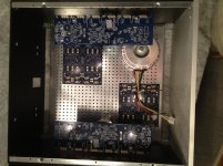
Just received the boards and 'Big Amp' Chassis..... now to work out the layout and order some bits.
quick initial questions :
- Is it recommended to mount the boards horizontal against the heatsinks ? just wondering if it would be more space efficient to mount them vertical ?
- For a dual transformer / power supply arrangement, would be better for weight distribution to mount one Rear Left, and the other Front Right. The power input would then be at the correct end of the boards.
Attachments
Just received the boards and 'Big Amp' Chassis..... now to work out the layout and order some bits.
quick initial questions :
- Is it recommended to mount the boards horizontal against the heatsinks ? just wondering if it would be more space efficient to mount them vertical ?
- For a dual transformer / power supply arrangement, would be better for weight distribution to mount one Rear Left, and the other Front Right. The power input would then be at the correct end of the boards.
Personally, I would "flat mount" the amplifier boards horizontal against the heatsinks, with standoff spacers similar to a computer motherboard (but I'd use slightly taller spacers than those). Flat mount (against the heatsinks) will effectively keep the small signal farthest away from the transformers. And the output devices would be really close to the bottom of the enclosure, so that, conveniently all the wiring hookup is within easy reach nearer the top of the enclosure (far away from transformers.
I'd make left channel cables exactly the same length as right channel cables.
And, personally, I would include a buffered preamp with a Bypass/Cancel switch for the front panel probably marked "turbo" so that preamp can be engaged for extra loud playback or bypassed/off for lower volume playback without the insertion loss of a preamp. Its just my personal theory that every high power amp needs a switched marked "turbo"
Last edited:
Thanks for comments. The chassis is so big, that I start to realise there are quite a few options for placement of boards + trafs inside. For the turbo idea, would the chassis also need a spoiler for this option?
What kind of supports are recommended to attach the pcbs to the heatsink?
Has anyone else checked Daniel's BOM mouser suggestions for the BOM boards ? Daniel, have you chosen these components for cost, or quality?
For the Dual Power Supply / dual traffo recommendations, I guess I need to read up on the Power Supply Forums.
- Home
- Amplifiers
- Solid State
- diyAB Amp The "Honey Badger" build thread