PJN, A word of caution: If you set your bias with the bulb tester in series your actual bias will likely be higher because your amps power supply consumption was limited to by the 40 watt light bulb in series. What I found is that 30mV with the bulb tester in series will quickly become 60+ mV once you remove the bulb tester and plug the amp straight into your receptacle. If you think about this it makes sense. I set my bias up to the noted 20mV and once everything looked good, I backed it way down and then plugged straight into receptacle. I then adjusted mine to 30mV as OS mentioned above. Jason
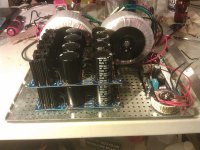
Working on my final layout. This is a DIYA 5U Deluxe chassis which will end up being stuffed to the brim. I still have to add the speaker protection board, which will float above the soft start, and the second PSU above the first.
Couple of questions- In a dual mono config, how important is having all the power wires the same length?
Also, this is a tight layout. Is it bad to have wires touching the PSU caps and heat sinks? I have to run some very close to them, they are of course insulated and also wrapped in heat shrink. I have no idea how hot the caps will get.
Attachments
You got it really tight. Don't forget that all wires have to be tightly twisted in pairs. With PS in the same case top objective with wiring is silence so sometimes wires must be a bit longer on one side than the other. Under normal operating conditions (not DJ environment) caps will not get much warmer than the environment (about plus 10-15C) although in your case everything is so tight. You may need to drill additional holes in the bottom of the case and its top as well.
When one really wants quality then four channels and active/passive crossover combinations are unbeatable. One box has two amps with single PS with two bridges and the other box has the other two with identical PS. One is left the other is right. It's more expensive but not that much as PS voltages can be lower so lower voltage caps can be used. There are still two toroids of higher power but price dofference is not that high. Two boxes but 3U each will do. Difference in sound quality however is substantial.
cheers,
You got it really tight. Don't forget that all wires have to be tightly twisted in pairs.
That's the trick, isn't it? Black from the toroids goes to the barrier box (front of pic), but red go to a totally different place, the soft start board. If space weren't an issue I could mount the ss board near the PEM and all would be good. But that means I'd have the small toroid for the speaker protection near signal wires.
Now, I am using teflon insulated, solid silver signal wires which should greatly reduce noise but I'm not sure how much I should worry.
Working on my final layout. This is a DIYA 5U Deluxe chassis which will end up being stuffed to the brim. I still have to add the speaker protection board, which will float above the soft start, and the second PSU above the first.
Couple of questions- In a dual mono config, how important is having all the power wires the same length?
Also, this is a tight layout. Is it bad to have wires touching the PSU caps and heat sinks? I have to run some very close to them, they are of course insulated and also wrapped in heat shrink. I have no idea how hot the caps will get.
If you can help it, I would keep the speaker protection away from the soft start as not to entice 60Hz AC from infiltrating your speaker output. Also, if you must stack the soft start and the speaker protection on top of each other be careful, those 5w resistors get pretty warm. I ran an infrared thermometer around the sand cast resistors and they get around 180-260 degrees Fahrenheit... You may want the soft start on top near the vents.
I am willing to bet that you can't hear the difference in your lengths of power lines--that is, unless you mount your amp boards on your cook top and run the leads from a PSU in your living room
 .
.I would keep the wires off as much as possible:
Jason
Attachments
Last edited:
Thanks. I'm planning to mount the speaker protection board perpendicular to the soft start but above it and to the opposite end of the resistors, so the 5Watters aren't covered by it. I do have enough room, and am considering a mu-metal shield under the speaker protection board.
Pretty comfy layout Rinnav. What are your PS and box dimentions?
I haven't got yet all parts but I got a 3U box (430x330x120mmm), which is not roomy. When building Stochino (four channels/two per box) I had to place toroids in a separate box.
My first HB module (two boards) I'd like to fit in one box. Toroid will be 625VA 2x46.5V d=145mm, alternative would be a 500VA toroid d=125mmm but 500VA is not much. Caps are: 6x15,000uF/80V 40x80mm plus soft start and speaker protection. I may not manage to fit everything in one box.
cheers,
Pretty comfy layout Rinnav. What are your PS and box dimentions?
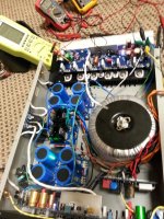
I am using a donor chassis and it is 360mm X 300mm X 120mm. It is tight but plenty of heat sink and and the only thing that gets warm is the soft start. I am using an AnTek AN-8445 teroid (800VA/2 X 45V, 1 X 18V and 1 X 12V) and the diameter is 152.4mm X 89mm in height. I am using 18V and 12V 2A secondaries to run the speaker protect and Halo LED on the power switch. My caps are 12,000uF X 8 and are 35mm X 60mm. To save space I stacked the rectifier boards/mounted the speaker protection and soft start on end. I had to get creative but you should have plenty of room!
Thanks Rinnav, so your box is even a touch smaller than mine. Maybe I'll manage to fit everything in it if I mount boards on heatsinks the same way as you did. It saves space but if something goes wrong or does not work fine it becomes troublesome. I like to have easy acces to both sides of boards. I think I know how to solve this problem - removable top mounted heatsinks with boards attached at 90 deg close to box sides.
cheers,
cheers,
Maybe I'll manage to fit everything in it if I mount boards on heatsinks the same way as you did. It saves space but if something goes wrong or does not work fine it becomes troublesome. I like to have easy acces to both sides of boards.
I thought about this so I added extra long TP leads. Once testing was complete, I slipped some red lead insulators over them (you can see these on the lower amp board in the above picture) to prevent inadvertent contact. When the boards are in the mounted position, R30 bias adjustment is slightly challenging--it tested just how steady my hands were but never slowed me down! I am a gluten for self inflicted pain.
I was pretty fortunate as the only thing that went wrong is that I had one LED on the PSU soldered backwards...
Jason
Last edited:
Something wrong with your description.That's the trick, isn't it? Black from the toroids goes to the barrier box (front of pic), but red go to a totally different place, the soft start board. If space weren't an issue I could mount the ss board near the PEM and all would be good. But that means I'd have the small toroid for the speaker protection near signal wires.
Now, I am using teflon insulated, solid silver signal wires which should greatly reduce noise but I'm not sure how much I should worry.
Electricity can ONLY flow around a circuit.
That circuit MUST come back to the starting point. It is not a circuit if it does not come back.
The Circuit has a Flow and a Return. EVERY circuit has a Flow and Return.
Your Soft Start Board MUST have a circuit to operate. It MUST have a Flow and Return!!!!!!
Here is the wiring diagram from the build guide. Red wires from the tranfos go to the softstart, black wires go to the PEM. What I meant was that I can't twist the red and black wires from the transfos together because the softstart board is not close to the PEM. Or am I missing something?
Attachments
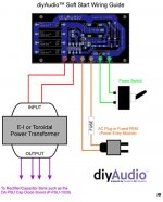
Each pair of AC wires should be twisted tightly together - the two (sometimes four) wires from the soft start to the transformer (red), the two wires from the soft start to the switch (green) and the two wires from the PEM to the soft start (orange). Similarly, twist the wires from transformer secondary windings to rectifier board(s) (purple).
You should also twist the DC mains wires from the rectifier(s) to capacitors if separate and capacitor bank to amplifier board including the ground lead.
You should also twist the DC mains wires from the rectifier(s) to capacitors if separate and capacitor bank to amplifier board including the ground lead.
Here is the wiring diagram from the build guide. Red wires from the tranfos go to the softstart, black wires go to the PEM. What I meant was that I can't twist the red and black wires from the transfos together because the softstart board is not close to the PEM. Or am I missing something?
Do you have dual primaries or single primaries? I used an AnTek 8445 and it has dual primaries (2 black and 2 red). For 120v, I placed (in parallel) both sets (2) of primaries to the Soft Start Board (red together and black together to the SS board). The white and black come from your PEM and connect to your Soft Start board. The ground from your PEM goes to the chassis for the entry ground. I just want to make sure you are wireing for 120v operation correct?
Do you have dual primaries or single primaries? I used an AnTek 8445 and it has dual primaries (2 black and 2 red). For 120v, I placed (in parallel) both sets (2) of primaries to the Soft Start Board (red together and black together to the SS board). The white and black come from your PEM and connect to your Soft Start board. The ground from your PEM goes to the chassis for the entry ground. I just want to make sure you are wireing for 120v operation correct?
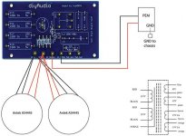
I do believe I had it wrong. Here is a diagram of what I intend based on feedback. Yes, two Antek AS4445 tranfos with dual primaries for 120v. Is this diagram correct? (I am not using a secondary switch, just the one on the PEM).
Attachments
Last edited:
Every pair of Flow and Return should at least be close coupled, but better is twisted.
That is EVERY pair.
This applies to: mains AC, Low Voltage AC, DC that varies, Signal wiring, etc.
BTW,
I do not recommend two transformer running from the same soft start resistor/thermistor.
I much prefer separate soft start resistor to feed each transformer and then a two contact relay (or two relays) to bypass these resistors.
I'm stacking my PSU's on top of each other. I need to raise the top one 60mm. My original thought was to use M3 standoffs, probably several screwed together to do so. I priced them and it's over $50 for a handful of them. I don't have room for a riser panel. Any other ideas? I'm considering threaded rod, which I could cut to length.
- Home
- Amplifiers
- Solid State
- diyAB Amp The "Honey Badger" build thread