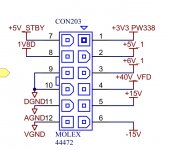
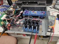
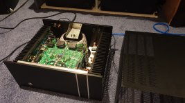
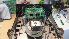
Made a little progress last night. I have the diyaudio psu boards. I ordered up some parts coming in the mail... But I wanted to try to take advantage of the arcam board that acts as a soft start for the transformers, as well as creates additional dc voltage sources. The board wants to be plugged into a large main cpu board that controls the relays for the transformers. Took me a little while, but I figured out how to trick the board into soft starting without the cpu board. So now I have a +5v, +6v, +15v, -15v, and what should be a +40v, but reads +52v. These can be used should I decide to add anything like an active crossover for a subwoofer channel, or supply voltages for the vu meters, and the fans under the heatsinks.
Next I need to figure out how to integrate the speaker protection board with the arcam speaker output board. It already has nice omron relays installed, and will mount against the opposite side of the case. The relays are 24v units. I should be able to adapt the diyaudio speaker protection board, sending it ac from the secondaries that are creating the 15vdc rails. How then can I use the 24v relays, instead of the 12v relays specified by the speaker protection board?
Next I need to figure out how to integrate the speaker protection board with the arcam speaker output board. It already has nice omron relays installed, and will mount against the opposite side of the case. The relays are 24v units. I should be able to adapt the diyaudio speaker protection board, sending it ac from the secondaries that are creating the 15vdc rails. How then can I use the 24v relays, instead of the 12v relays specified by the speaker protection board?
Attachments
Last edited:
Sandrohv,
You have done extensive simulations of HB and found out that its slew rate was only 25V/us so the question is: what could be done to increase slew rate of Honey Badger?
I have redesigned an amp which is a combination of Blameless and Honey Badger to get slew rate up to about 40V/us. I do not know if I have succeeded so I'd appreciate if you commented on it. Its asc file is attached.
Of course I invite everybody here on commenting as well.
cheers,
Attachments
Hi Janusz, what is a blameless amp? To my knowledge, a blameless amp is an amp that has had the major distortions taken care of (Doug Self's defition), so I am not sure what you mean with a 'Blameless'. Sorry to pick on you on this, but I see a lot of members who refer to the 'Blameless' as a topology when there is no such thing. Blameless is a concept.
Regarding slew rate, lets start with the basics:
SR = I_TAIL / CC
where I_TAIL is IC_Q7 and CC is C7*C8/(C7+C8) = ~ C7.
Now, something else to be aware of is:
BW = GM / CC / 2pi / Acl
where GM is the transconductance of the input stage, and ACl is the close loop gain ~40.
Finally, GM = 1 / (R15 +re_Q2) = ~1/R15 since R15 = ~10 re_Q2.
Here is what you can do:
Since SR = I_TAIL / CC, then you can
- Increase I_TAIL, but you need to watch out for the voltage across the current mirror resistors R20, R21. If this voltage is too large, specially under slew conditions, Q5 can saturate. You can reduce R20, R21 proportionally to the increase of I_TAIL, but you will have a noise penalty.
- Decrease CC by decreasing C7. In this case you will also need to decrease GM to not have the BW of the amp increase on you and potentially drive it to instability. In this case, you can increase R15 to dial the BW down. Again, by increasing R15 you will get a noise penalty.
Hope this helps,
Best, Sandro
Last edited:
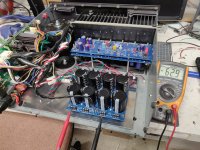
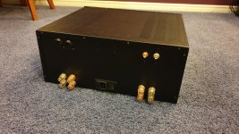
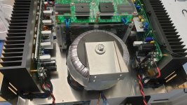
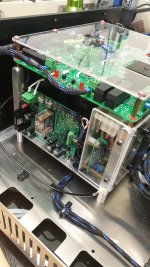
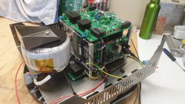
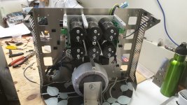
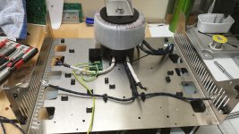
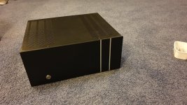
At risk of posting too much due to excessive enthusiasm on my first amp build... I got the power supply sorted. I still have to figure out exact mounting location, and then shorten the wires, but the power supply seems to be sorted. However only one diode on the psu lit up. Diode in the wrong way? I am using a single monolithic bridge rectifier. Transformer is center tap with the center tap going straight to ground on the psu board.
But anyway, voltage! Rails are steady at +-62.9V. I managed to retain the arcam soft start board and power switch, and standby transformer. I installed a platform on the base made out of aluminum that will hold the cap board, the rectifier, and have lots of space left over. I have an extra set of secondaries off of the arcam transformer that should provide +- 30v rails for... Something down the road.
Anyways, stoked.
Attachments
Hi Janusz, what is a blameless amp? To my knowledge, a blameless amp is an amp that has had the major distortions taken care of (Doug Self's defition), so I am not sure what you mean with a 'Blameless'. Sorry to pick on you on this, but I see a lot of members who refer to the 'Blameless' as a topology when there is no such thing. Blameless is a concept.
Regarding slew rate, lets start with the basics:
SR = I_TAIL / CC
where I_TAIL is IC_Q7 and CC is C7*C8/(C7+C8) = ~ C7.
Now, something else to be aware of is:
BW = GM / CC / 2pi / Acl
where GM is the transconductance of the input stage, and ACl is the close loop gain ~40.
Finally, GM = 1 / (R15 +re_Q2) = ~1/R15 since R15 = ~10 re_Q2.
Here is what you can do:
Since SR = I_TAIL / CC, then you can
- Increase I_TAIL, but you need to watch out for the voltage across the current mirror resistors R20, R21. If this voltage is too large, specially under slew conditions, Q5 can saturate. You can reduce R20, R21 proportionally to the increase of I_TAIL, but you will have a noise penalty.
- Decrease CC by decreasing C7. In this case you will also need to decrease GM to not have the BW of the amp increase on you and potentially drive it to instability. In this case, you can increase R15 to dial the BW down. Again, by increasing R15 you will get a noise penalty.
Hope this helps,
Best, Sandro
Thanks Sandro,
Yes, Blameless is a concept Douglas Self explained in his book. DX Destroyer took it here and designed his DX Blame amplifier. As I got a number of boards designed by Alex for that amp I decided to modify it exploiting Douglas' ideas of how to increase slew rate of that kind of amplifier. I also decided to use Honey Badger design of the output including drivers and its VAS rather that DX although these are almost identical.
In simulation this combination of DX Blame and Honey Badger gives better performance than DX Blame and theoretically should be substantially faster than Honey Badger. I intend to use this amp to drive my 4 ohm woofers covering 80-450Hz range. As above that I'll be using much faster amps than any of these i wanted to improve slew rate of the woofer amp as well.
One more question - what do you think of that combination of modified DX Blame and Honey Badger? What changes would you recommend?
cheers,
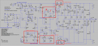


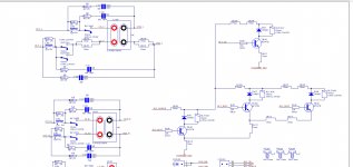
Without any major re-design, a few ideas in the screenshot.
Do you have a link to the original DX Blame Amplifier?
Hi Sandro,
Thanks for your comments. The problem I have is that I can do only these mods which would fit boards I have. Instead of diodes if I manage I think I'll insert capacitance multipliers.
What sort of current limmitter would you suggest? I was thinking about cascoding VAS but the board is very tight. Two pole compensation is not a problem and improves amp's performance at high frequencies but it will be used only below 500Hz so Miller is good enough.
Links to the original DX Blame mk III amp threads:
1. this one has been closed but it is about designing this amp: Dx Blame MKIII-Hx - Builder's thread
2. Build thread continued in 2013: DX Blame MkIII - 2013 builders thread.
cheers,
Last edited:
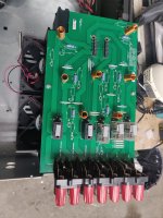
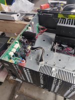
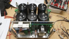
Finished My First Amplifier Build
Hi Guys,
Well it's taken me nearly 4 years to plan and build this Honey badger.
I hope you guy's like the final build photos.
If you wish to see more I have included a link to my entire build album.
First Amplifier build - Google Photos
Enjoy.
Hi Guys,
Well it's taken me nearly 4 years to plan and build this Honey badger.
I hope you guy's like the final build photos.
If you wish to see more I have included a link to my entire build album.
First Amplifier build - Google Photos
Enjoy.
Attachments


the super leach aka double barreled had a SR pf 80volts/microsec on an 800khz bandwidth....
Stoccino has a design with 300v/us using latfets as outputs...
Yes, higher (possibly regulated) voltage on the input and VAS certainly has merits and it's not difficult to implement although somewhat more expensive.
I got Stochino. Fast amps sound better. I remember when in 1980s Electrocompaniet introduced its 100V/us amp. Even half deaf could hear the difference as amps of that time rarely had SR higher than 20V/us. A friend of mine has among other stuff the whole Electrocompaniet system from sources to the power amp plug into electrostats. Very clean and balanced sound.
cheers,
- Home
- Amplifiers
- Solid State
- diyAB Amp The "Honey Badger" build thread