If you want a more rigid wire you may use the central conductor of RG6 coax (CATV coaxial cable ) .
Do you mean for signal? Or power? Or did I misunderstand
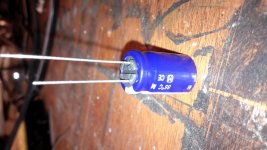
Can be used for signal ... I use this wire to support resistors of course in series with a resistor resistance of the wire have no effect ...
Look at the wire with a blue shrink to keep th 0.22 ohm in place it is a copper plated steel wire
Very pretty amp !
If you did everything right , you will be amazed how this thing "cranks" !
I built and tried to bring my pair to death before I moved on to my slews.
I could not kill it.
OS
Since you have your R32/R33 jumpered with wires , you will have worse
PSRR. No stability issues , but less performance.
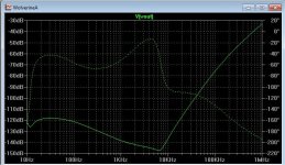
The way it is = -67db PSRR at 1K
22R for R32/33 = -95DB
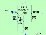
If you add 2 capacitance multipliers between The R32/33 (pads/pins) like the example :
(below 1) .... your PSRR becomes excellent. -120db is an audible improvement.
Any Badger builder can use this mod ...... but you will lose 2 volts of
amplifier headroom before clip. Still , not a bad tradeoff !!
Negative rail is just a simple PNP version of the example.
PS- this simple enhancement is 90% of the wolverine improvement over the badger.
The stereo image will be noticeably improved. Even in a dual mono setup ,
the general audible detail will also be enhanced.
OS
PSRR. No stability issues , but less performance.
The way it is = -67db PSRR at 1K
22R for R32/33 = -95DB
If you add 2 capacitance multipliers between The R32/33 (pads/pins) like the example :
(below 1) .... your PSRR becomes excellent. -120db is an audible improvement.
Any Badger builder can use this mod ...... but you will lose 2 volts of
amplifier headroom before clip. Still , not a bad tradeoff !!
Negative rail is just a simple PNP version of the example.
PS- this simple enhancement is 90% of the wolverine improvement over the badger.
The stereo image will be noticeably improved. Even in a dual mono setup ,
the general audible detail will also be enhanced.
OS
Attachments
Last edited:
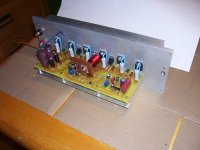
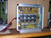
The picture you see in post 2103 is a unfinished unit.
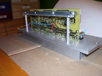
I did build a pair of module and build a stereo power amplifier using a common power suply.
I ad a typical protection circuit on a extra board, and also a single ripple filter for input stage of the 2 chanels.
You may see theses extra boards on the pictures below.
I did build a pair of module and build a stereo power amplifier using a common power suply.
I ad a typical protection circuit on a extra board, and also a single ripple filter for input stage of the 2 chanels.
You may see theses extra boards on the pictures below.
Attachments
There are quite a few/many variations still coming out.
Can any of these be fitted to the adaptable Forum PCBs?
Could you show pics of how to place components to achieve each variation?
Using 22R for R32/R33 is not a mod. That was the original design which
gives acceptable PSRR.
My capacitance multiplier suggestion (or fully separate supplies) are optional
and are so simple. They are just a few passives and a semi. A perfboard
for each rail with the multiplier grounds to the Badger star would suffice.
One could get fancy and make make daughter cards to fit the R32/33 pads , but
this would be up to the builder.
This capacitance multiplier is on 500+ amps now - it works. The other mods
are minor and are just to make this blameless "friendlier" to an EF3 OPS.
A builder capable of finishing this project should have no issue negotiating
a couple multipliers.
")
OS
Yep, been doing it for about 45 years - until I discovered the little plastic bending jigs. They work well 99% of the time, but the needle-nose are still useful. Gotta have needle-nose pliers on your bench for sure.Here's the easy way to bend resistor leads neatly. Once you figure out the magic spot on the needle nose pliers, the leads will fit perfect every time.
Rick
I have been digging around and discovered that Dupont shows a Kapton film (30HN) with a thickness of 7.6uM / 0.3mil.
Not sure if the material is too difficult to work with for heatsink duties ?
This would seem to Increase thermal conductivity by a factor of 3 over the 1mil Koptan stuff.
Does anybody have application experience with this very thin film ?
Not sure if the material is too difficult to work with for heatsink duties ?
This would seem to Increase thermal conductivity by a factor of 3 over the 1mil Koptan stuff.
Does anybody have application experience with this very thin film ?
the ratio of R40:R41 gives the proportion of input voltage at the base/gate of the series element.
the 470r:47k gives 1:0.9900990099
i.e. 99% of the input is applied to the base.
The output is one Vbe below that 99% value.
The difference between input and output is thus Vbe+ (a %) and this appears as Vce
The Vce is what allows the multiplier to work with a ripple on the input. If Vce becomes too small then the multiplier does not work properly.
Many poor designers forget to include R40 (the 47k) and this error in the multiplier topology results in poor ripple attenuation when the lower Vce allows the series transistor to become saturated.
Typical percentages for that resistor ratio are from 90% to 95% when ripple is high. The 99% used here should be reserved for low ripple supplies.
The time constant of R40 & C26 (10seconds) sets the attenuation of low frequency ripple.
I was just paying around with a "dry fit", and am curious about mounting "Q13" to the main heat sink.
I have the pre-drilled 5U Deluxe chassis. According to the universal mounting specifications on the DIYA Store website (and physically on my heat sinks), the hole I need is not available on the 400 mm chassis, only on the 300 mm.
The hole would be located directly in the middle of where the two heat sinks come together... Am I missing something?
- Home
- Amplifiers
- Solid State
- diyAB Amp The "Honey Badger" build thread