Hi everyone,
I have built my own class-B audio amplifier and in simulation it looked good. However in testing, when I connected it up and switched the power on, the resistors at the emitters of my current mirror were smoking and I don't understand why.
I tested first with no load and no input, just to see what the dc conditions were like. It is a 100W amplifier and I am using +- 50V for the supply. Does anyone know any reasons why these resistors are getting too hot?
Thanks
Michael
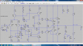
2N2369, apart from coming in a TO-18 case, have a Vceo of 40V. Rail to rail, they could see 100V. They have probably failed short.
Consider using 2N5401/2N5551 for your small signal parts. Also your VAS and it's current source transistors Q6 and Q12 need to be of a higher rating. MJE340/350 work OK and are cheap.
Consider using 2N5401/2N5551 for your small signal parts. Also your VAS and it's current source transistors Q6 and Q12 need to be of a higher rating. MJE340/350 work OK and are cheap.
2N2369, apart from coming in a TO-18 case, have a Vceo of 40V. Rail to rail, they could see 100V. They have probably failed short.
They're diode-connected. Not likely to see Vcc unless something else is badly wrong. The LTP and the current source have to stand off rail voltage. And even then it wouldn't go much more than one Vcc.
R7 may well have got hot but after R3 and R4 started smoking I disconnected the supply and only felt if the current mirror was hot (it was warm). I've never used current mirrors before but from books that I've read the transistors I used should be fine, unless there is a fault in one. The circuit drew a low current from the supply with no load or signal, which from my experience normally means the circuit is connected ok. I'm just struggling to see why so much current is going going through these resistors to make them smoke!
I suggest that you review the output drivers and output devices. They are ok for lower voltage rails than 50 volts but will be a potentially fail at the voltages you propose.
Experience is also that there are some really good options for these that are both available and cheap. Look at mje15030 series for drivers and mjl21193 series for outputs. These are good performers (unlike the aged 3055) and are also nigh on indestructible!
By the way the general topology of your amplifier is a good start. Will be stable and will work well.
As an aside at this point you want to be able to explain to yourself "why did I have to replace those transistors" in working this out you are likely to find something that is valuable to you!
Have fun - building stuff is in my mind a good part of learning.
Experience is also that there are some really good options for these that are both available and cheap. Look at mje15030 series for drivers and mjl21193 series for outputs. These are good performers (unlike the aged 3055) and are also nigh on indestructible!
The only reason I'm using the 3055 and 2955 is that they are the best ones available at my university for the output stage. I am looking into ordering so better quality transistors but my initial goal was to build a cheap amplifier using resources my university provides. However I have forked out around £70 on speakers, transformers etc.
This only my 2nd amplifier so I still have a lot to learn!
- Status
- This old topic is closed. If you want to reopen this topic, contact a moderator using the "Report Post" button.
- Home
- Amplifiers
- Solid State
- Current Mirror emitter resistors smoking