Thanks Andrew . It needs saying . Doing the right things for the wrong reasons is something we should fight to change . If not the" I only listen " people are more right . I know Dvv likes boosted op amps .
This is not science , however it is evidence . Some call a VAS a Trans-impedance stage . Even that says be careful ? Doubt it is exactly one nor the other . It is both?
I think 6 V/uS is right for 100 watts . My own amp is 45 V/ us / 100 W . I would feel uneasy dropping back to 6 .
This is not science , however it is evidence . Some call a VAS a Trans-impedance stage . Even that says be careful ? Doubt it is exactly one nor the other . It is both?
I think 6 V/uS is right for 100 watts . My own amp is 45 V/ us / 100 W . I would feel uneasy dropping back to 6 .
I like that .
This amp thread I think has turned into a minimalist perfect amp , almost blameless . That is plainly contentious and I apologies in advance . What it allowed was skills we almost forgot we had directed at a Lethiathan . The owner of the design made us question some of our near religious belief . For a beginner courage to resit criticism was what I saw . I have a hunch we all would live happily with this amp ? It probably at no great cost ( $50 in US/UK ) has 30 % more performance to give ? That's probably 5 years work as it will be all be by ears if not owning an Audio Precision test station . Even then ears will be quicker . PSU would be my best bet . Remember unregulated is fast . It isn't always the less good choice . I think capacitors close to each output transistor might be good ? 1000 uF ? Even cheap will do something . They need returning to ground carefully if so .
This amp thread I think has turned into a minimalist perfect amp , almost blameless . That is plainly contentious and I apologies in advance . What it allowed was skills we almost forgot we had directed at a Lethiathan . The owner of the design made us question some of our near religious belief . For a beginner courage to resit criticism was what I saw . I have a hunch we all would live happily with this amp ? It probably at no great cost ( $50 in US/UK ) has 30 % more performance to give ? That's probably 5 years work as it will be all be by ears if not owning an Audio Precision test station . Even then ears will be quicker . PSU would be my best bet . Remember unregulated is fast . It isn't always the less good choice . I think capacitors close to each output transistor might be good ? 1000 uF ? Even cheap will do something . They need returning to ground carefully if so .
to Power Ground right next to the output devices............ They need returning to ground carefully if so .
I like that .
This amp thread I think has turned into a minimalist perfect amp , almost blameless . That is plainly contentious and I apologies in advance . What it allowed was skills we almost forgot we had directed at a Lethiathan . The owner of the design made us question some of our near religious belief . For a beginner courage to resit criticism was what I saw . I have a hunch we all would live happily with this amp ? It probably at no great cost ( $50 in US/UK ) has 30 % more performance to give ? That's probably 5 years work as it will be all be by ears if not owning an Audio Precision test station . Even then ears will be quicker . PSU would be my best bet . Remember unregulated is fast . It isn't always the less good choice . I think capacitors close to each output transistor might be good ? 1000 uF ? Even cheap will do something . They need returning to ground carefully if so .
In all truth, Nige, that was not courage, that was a mad rush to get it up and going at any cost. Just count the rather obvious revisions made since its introduction. He is young and reckless, as most youth is.
For a beginner, what I saw was resillience to suggestion asked for. He had it up and running in what I believe is a suboptimal form in no time, which makes me wonder why did he bother asking for suggestions at all when he had no intention of including any serious change.
The only thing that sets him apart from a myriad of similar amps all over the Internet is the fact that he used a triple output stage, predriver, driver, output devices. That is, unfortunately, all too rare.
That said, one has to salute his drive and the work he did, even if he's 100% locked to the notion that low THD figures define sound quality.
@Aniket:
Obviously, I am a bit older than you, I just turned 60. In all honesty, at the time I was your age, I was more careful and less rushed, but remember that at the time (late 70ies) we had no smulators and had to do it all by hand. Thus, mistakes were much more costly, so we had to try harder to make as few as we could.
So, please understand my comments as per that old story:
Father and son bull are standing on a hill and watching a herd of cows graze.
Son bull says: "Hey dad, let's stampede down the hill and bang a cow each."
Father bull replies: "No son, let's STROLL down the hill and bang all the cows."
Last edited:
I like that .
This amp thread I think has turned into a minimalist perfect amp , almost blameless . That is plainly contentious and I apologies in advance . What it allowed was skills we almost forgot we had directed at a Lethiathan . The owner of the design made us question some of our near religious belief . For a beginner courage to resit criticism was what I saw . I have a hunch we all would live happily with this amp ? It probably at no great cost ( $50 in US/UK ) has 30 % more performance to give ? That's probably 5 years work as it will be all be by ears if not owning an Audio Precision test station . Even then ears will be quicker . PSU would be my best bet . Remember unregulated is fast . It isn't always the less good choice . I think capacitors close to each output transistor might be good ? 1000 uF ? Even cheap will do something . They need returning to ground carefully if so .
Many thanks Nigel,
for all your praises, there are 3 main caps for onboard rail filtering, i have installed 470, 220 and 100uF 63V caps and two snubber caps, 0.47uF and 0.22uF 100V. also 220uF and 0.22uF for VAS and input stage rail filtering after the diodes.
In all truth, Nige, that was not courage, that was a mad rush to get it up and going at any cost. Just count the rather obvious revisions made since its introduction. He is young and reckless, as most youth is.
For a beginner, what I saw was resillience to suggestion asked for. He had it up and running in what I believe is a suboptimal form in no time, which makes me wonder why did he bother asking for suggestions at all when he had no intention of including any serious change.
The only thing that sets him apart from a myriad of similar amps all over the Internet is the fact that he used a triple output stage, predriver, driver, output devices. That is, unfortunately, all too rare.
That said, one has to salute his drive and the work he did, even if he's 100% locked to the notion that low THD figures define sound quality.
@Aniket:
Obviously, I am a bit older than you, I just turned 60. In all honesty, at the time I was your age, I was more careful and less rushed, but remember that at the time (late 70ies) we had no smulators and had to do it all by hand. Thus, mistakes were much more costly, so we had to try harder to make as few as we could.
So, please understand my comments as per that old story:
Father and son bull are standing on a hill and watching a herd of cows graze.
Son bull says: "Hey dad, let's stampede down the hill and bang a cow each."
Father bull replies: "No son, let's STROLL down the hill and bang all the cows."
Hi dvv,
Firstly, i couldn't have had a working help without your teachings.
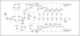
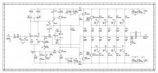
I agree, this amp is done in a hurry, and there were some changes made in the schematic. I believe to evolve the design, after all this is my very first design. I have attached both the original schematic that was proposed earlier and the updated working schematic which I am using now. please take a look by how much it has changed. none of the changes in the amp topology. small changes have been done like the emitter resistors of the LTP and current mirror have been reduced, VAS current increased, base stopper resistors of the output stage were increased. nothing else. also suggestions didn't came so early.
please go back to post #172 http://www.diyaudio.com/forums/solid-state/211635-simple-100w-power-amp-18.html#post3499093
amp was working perfectly with the original schematic earlier but with only one output transistor. now, view post #196 http://www.diyaudio.com/forums/solid-state/211635-simple-100w-power-amp-20.html#post3504338
amp was oscillating when all four output transistors were placed in the circuit.
Till now, this question is unanswered that why the amp was working perfectly with 1 output transistor with the original circuit and oscillating with all 4 outputs. and this my question is not only pointed to you Dear dvv. i was rather demotivated when my amp performed this way. then, after this all the suggestions and scoldings came, which ultimately made the updated working schematic. I am very happy that this design has evolved to perform what it was originally intended for. this is my first ever design, please bear with me.
")
Thanks and Regards,
Aniket
Attachments
A possible - and I think very probable - reason why it worked with a single pair but osciallted with 4 pairs is insufficient current drive. Quite simply, when you drive multiple pairs of output devices, you WILL need more predriver and driver current.
Sometimes, this added extra can be surprisingly little more, not like +50% or some such, but rather like +5% even. Remember, with multiple pairs, you also have multiple capacitances of each parallel pair added on.
Many times, moving on from one to two pairs can be done as is - witness the industry models. But from 1 to 4 pairs is a bit much, you simply must expect that you will need to change a few things. In this respect, MOSFETs are most forgiving, since they are voltage driven anyway, although of course, parallelong MOSFETs has it own problems.
Not that any of it matters much - you have it up and running, and to me, you seem satisfied. THAT'S what it's all about.
"I think 6 V/uS is right for 100 watts "
The Marsh and Jung criteria suggest between 0.5V~2V per peak volt of output. That would be more like a minimum of 20V/µS for a 100W/8Ω amplifier.
Running out of drive current usually makes the waveform look like someone took a bite out of it in the 2nd and 4th quadrants.
The small power supply bypass caps (less than 1µF) may well need low values of resistors in series with them to stop oscillations. They also need to be grounded at the point the load current is consumed (speaker ground). This is generally impractical, and the inductance in the leads and traces leads to oscillations, and the series resistance de-Q's the resonances leading to the oscillations.
"I think 6 V/uS is right for 100 watts "
The Marsh and Jung criteria suggest between 0.5V~2V per peak volt of output. That would be more like a minimum of 20V/µS for a 100W/8Ω amplifier.
Running out of drive current usually makes the waveform look like someone took a bite out of it in the 2nd and 4th quadrants.
The small power supply bypass caps (less than 1µF) may well need low values of resistors in series with them to stop oscillations. They also need to be grounded at the point the load current is consumed (speaker ground). This is generally impractical, and the inductance in the leads and traces leads to oscillations, and the series resistance de-Q's the resonances leading to the oscillations.
That's exactly the number we sort of agreed with on a related discussion some time ago, and John Curl said he'd go for 40 V/uS just in case. I agreed then and I agree now.
I do feel fast amps do sound better, but as ever, there's a limit to what is necessary to achieve what a design is capable of. Going much above that limit is simply wasted time and work.
Much the same applies to quiescent (bias) current. By trial and error, I found that most amps will benefit from increased bias current to about 110-130 mA per transistor. You reach a point after which you can add more but you will get nothing in return, meaning that the only really meaningful step above a certain point is only going full pure class A operation.
...
The small power supply bypass caps (less than 1µF) may well need low values of resistors in series with them to stop oscillations. They also need to be grounded at the point the load current is consumed (speaker ground). This is generally impractical, and the inductance in the leads and traces leads to oscillations, and the series resistance de-Q's the resonances leading to the oscillations.
An excellent way to reduce the possibility of oscillation is to marry a medium sized cap to the collector of ech output device, as near to the device as possible.
Nige asked about 1,000 uF, I'd rather see that as 2,200 uF - bigger, with more current potential.
This is the same as I have been recommending.An excellent way to reduce the possibility of oscillation is to marry a medium sized cap to the collector of ech output device, as near to the device as possible........
But where does the other cap lead go?
I have my theory that I use and have posted it, but I would like to hear your recommendation.
This is the same as I have been recommending.
But where does the other cap lead go?
I have my theory that I use and have posted it, but I would like to hear your recommendation.
To the ground, of course, where else, Andrew? The PSU ground, that is.
to Power Ground right next to the output devices.
I often use flying wires to TO 3 devices when I build prototypes . One has to be more careful if so . Being that the output device is a current amplifier usually it causes no problems and can facilitate an amp like here . I think saying be careful covers it . It is that I am moving slightly away from conventional thinking when adding local decoupling and if you like Formula 1 KERS . Thus I am apologizing in advance for complications it might bring . Small ones I am sure ? Sad to get it wrong as this is a very big deal and cheap . Panasonic 1000 uF FC series 63V if compatible seems where to start ?
I suspect a Star arrangement to be best ? I use a big brass bolt and eye tags when I do it ( 4 mm nickle platted , silver would be better I am sure ) . It looks like a flower . If the PCB has a big ground plane that might be better ? Solder to any point I guess ? I have never done this so can not say if it works well . I have looked at 3 layer PCB as the people I work with do it all the time . If doing home brew PCB I think it is possible to do 3 layer . Just make 2 PCB's and bring them together .
The Douglas Self's advice on Star is helpful . However my test show that it is not as easy as said . Sometimes doing the wrong thing works better ! The spectrum analyzer will say it sometimes . Even the way the analyzer is connected to the circuit can give false results . It is difficult . As DF 96 said simulators assume superconductors sometimes .
If doing it the wrong way works better it can mean a rethink will get the right way to work better still . Williamson in 1947 ( aged 19 ? ) said sometimes a Star is not possible . If so an intelligently used bus-bar is good . When I build valve amps I keep them simple so as to have Star . Also I try not to use a PCB .
"I think 6 V/uS is right for 100 watts "
The Marsh and Jung criteria suggest between 0.5V~2V per peak volt of output. That would be more like a minimum of 20V/µS for a 100W/8Ω amplifier.
Running out of drive current usually makes the waveform look like someone took a bite out of it in the 2nd and 4th quadrants.
The small power supply bypass caps (less than 1µF) may well need low values of resistors in series with them to stop oscillations. They also need to be grounded at the point the load current is consumed (speaker ground). This is generally impractical, and the inductance in the leads and traces leads to oscillations, and the series resistance de-Q's the resonances leading to the oscillations.
As I have said in other threads I think it is greate advice that isn't fact based . If you like Malaria . London had the " bad air " idea for illness . The sewers built by Bazalgette are still in use today . They just about slew enough today . He used Portland cement which was experimental . Good that he did as these sewers are still working with serious modern flows . Almost like Techno music ? It is said to need high slew rates and crest factor allowance .
The last point is excellent . Dvv and I debated this in another way . I think your reason is the true reason and the resistor is required . A 1 R series resistance to the 1 uF if doing it without test gear ? To make an improved electrolytic into a device with a snubber seems Ideal . I did it on a 500 V capacitance multiplier recently . It was a hunch I just could not ignore . No evidence for any need . I just thought the resistor would do more good than harm . I used the well tested Zobel type of 10R + 0.1 uF . I had a bag of caps to use at no cost so did it . X2 suppression caps . I see no reason to use Audiophile ones . 2 x 220 nF in series at 500 V . Usual rating 385V DC per cap .
But where?
You have told us precisely where to start, the device collector (for an EF).
Where is the HF decoupling Ground relative to the device and/or relative to the MF decoupling Ground?
Andrew, I have always used the PSU ground for decoupling from the PSU. This method has never failed me.
I have on several occasions also tried a special grouning line to the central star earthing point, but I feel I have gained nothing but complication.
Nice in theory, but in practice, nothing to write home about.
However, all that said, I must remind you that by default I use separate PSU lines for the input stage and the VAS on one hand, and the current gain stage on the other. Also, much along what Niogel's been talking about lately, rather than use a relatively complex discrete voltage regulator, I tend to use a "virtual battery" type of regulation, based on either Motorola/ON Semi MJE 15031/15032 BJTs or IRF 510/9510 MOSFETs. The MOSFET version is more finnicky because of fairly large voltage drops across the MOSFETs, but that's not really a problem if one plans for it from the outset.
How long is that route during a half cycle of an AC waveform?Andrew, I have always used the PSU ground for decoupling from the PSU. This method has never failed me.
i.e. how far away is the PSU ground from the output devices?
How long is that route during a half cycle of an AC waveform?
i.e. how far away is the PSU ground from the output devices?
Fairly near. Very near if you count the upper side ground plane. Let's say about 1 cm on average.
Remember, it's not so much proximity as it is trace width and overall area of leads. Thicker copper plating also helps. I mean, the industry routinely works with 35 uM of copper, better models use 50 uM, and I use 70 uM. If I could lay my greedy hands on some Mil Spec 120 uM glass fibre, I would commit a crime and nick it.
- Status
- This old topic is closed. If you want to reopen this topic, contact a moderator using the "Report Post" button.
- Home
- Amplifiers
- Solid State
- Simple 100W power amp