This is what sreten pointed out; R81,82 has been removed completely
and still the bias is too low, so replacing it as I first thought, like you,
won't work. You only have R83,84 to reduce or R85,86 to increase.
It's a voltage divider in a sense.
Hi,
I thought I'd pointed out also the two test points are a dreadful place
to attempt to measure the bias, I mentioned two other better options.
Shorts are never dead shorts due to finite track and soldering resistances.
The test points are useless in terms of measuring bias without the 130R.
rgds, sreten.
I doubt such a machine would have been used on low volume production.
But who knows, all links seem to be named X.. and close by is another
0R resistor in the position named X30/X31.
Hi,
Well IMO it clearly has, as it has in my Audiolab. Otherwise simple wire
links would be cheaper if hand assembled, and the board layout would
not need to stick to standard resistor lengths for the wire links.
rgds, sreten.
Yes sreten, picked that point up in post#12. Without knowing what the OP read or understood of the procedure, it's difficult to know what he measures. However, it's not likely that with R81(130R) + R83(680R) in that arm of the divider that V(130R) was only 5-8mV in the version referred to by the manual, so I can't imagine those trimming posts were identified as test points.
I assumed he had found the output emitter resistors and they would surely have been specified in the manual. I also understood his comment in #1 to mean he was simply testing what the 0R links were. Perhaps not - we await his return.
I assumed he had found the output emitter resistors and they would surely have been specified in the manual. I also understood his comment in #1 to mean he was simply testing what the 0R links were. Perhaps not - we await his return.
The trim resistor R81,82 has been removed in manufacture so the service manual is simply wrong for this board. The bias sub-circuit increases current in the bias transistor to reduce bias voltage across bases Q27,29 and Q28,30.
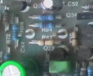
But R81/82 have not been removed! R81/R82 are NOT the 220R resistors that we have seen sitting high up in between the pins in the very first picture (close up) because in the overview picture in pampalini's second post, you can see they're not there.
The way I see it is that the silkscreen R81/82 is closest to the 0R resistors, and that the pins themselves have no reference designator. They are parallel to R81/R82, though, that's where they're drawn in the schematics.
That makes the situation as follows:
R81/82 schematics: 130R - but here: 0R;
R83/84 schematics: 680R - but here 920R;
R85/R86 schematics: 3k6 - but here 2k6.
The fact that R81/R82 are 0R explains why parallelling them as no effect and why pampalini measured 0R between them, had they been 130R, the instructions in the service manual would have been useful. That's why I suggested replacing all resistors first. And yes, it's also why measuring there would be no good.
Attachments
Last edited:
Hi,
Well IMO it clearly has, as it has in my Audiolab. Otherwise simple wire
links would be cheaper if hand assembled, and the board layout would
not need to stick to standard resistor lengths for the wire links.
rgds, sreten.
The fact that 0R resistors are in place of simple wires means very little. I work in industrial electronics manufacturing and we use these 0R resistors all the time. And no, we don't have a component stuffing machine for through hole devices.
Finding 0R resistors on a pcb might mean no more than that the client has specified them in their BOM rather than wire.
Last edited:
Just a quick reply....First of all thank everybody fo te help!
I did mesaured, as stated in the service manual, the bias across the big white .22 ohm resistor (part A).
The 220 ohm you see in the pix is my attempt, once again as stated in the service manual, to increase the bias. But, as the 81/82 resistor in my unit is 0, putting a 220 ohm resitstor in parallel, provide no effect to the bias current.
..so, once at home, I will measured the resistors, compare them with the list in the SM, and then think what to do....
Beware that measuring in-circuit of resistance values probably leads to different readings than what is expected on the basis of the colour-coding on the resistors.
The values I stated are based on what I could see in the very first close up pic in this thread.
The values I stated are based on what I could see in the very first close up pic in this thread.
Last edited:
Sure, the actual values of R83,84 and R85,86 appear to be different from the schematic - I cannot be certain what they are but R81 is gone. It is now a link.
My reasoning regarding the manual refers to the original design which it appears to do also so the bias adjustment according to the manual and attempted by the OP didn't do anything. I think that's clear enough.
`
My reasoning regarding the manual refers to the original design which it appears to do also so the bias adjustment according to the manual and attempted by the OP didn't do anything. I think that's clear enough.
`
Tiefbassuebertr. has just bumped up this old thread http://www.diyaudio.com/forums/solid-state/82499-cyrus-one-4.html with a familiar pic.
To simplify the whole discussion and make it easier for Pampalini, assuming values are correct, just place a 10k resistor across R83 (briefly) and post result.
To simplify the whole discussion and make it easier for Pampalini, assuming values are correct, just place a 10k resistor across R83 (briefly) and post result.
Last edited:
Sure, the actual values of R83,84 and R85,86 appear to be different from the schematic - I cannot be certain what they are but R81 is gone. It is now a link.
OK, sorry, I misunderstood the meaning of "gone" here.
Found in another thread started by pampalini that C53-C56 are also not according to the schematics.
I can't say that I like this practice of not updating the service manual with every new issue. Or is it that "issue 1" in the sideline in the schematic posted by pampalini actually does refer to the Cyrus One issue 1 and that a service manual issue 7 also exists?
Last edited:
Hi Jitter,
Well, that was the "only" difference I found in my unit...but somewhere in some forum I saw other people stating that they have the same 220uF caps, instead of the 100uF....
I was also guessing that also this could be relate to the bias issue. Those caps are the one close the the power transistors.
Well, that was the "only" difference I found in my unit...but somewhere in some forum I saw other people stating that they have the same 220uF caps, instead of the 100uF....
I was also guessing that also this could be relate to the bias issue. Those caps are the one close the the power transistors.
OK, sorry, I misunderstood the meaning of "gone" here.
I seems that C53-C56 are also not according to the schematics in pampalini's Cyrus One.
Personally, with all these discrepancies between service manual and actual device creeping up, I'd stay off the bias current. Who's to say that the bias current stated in the service manual is still valid for your version of the amp?
Perhaps now would be a good time to contact Cyrus.
Perhaps now would be a good time to contact Cyrus.
Last edited:
I totally agree with you! The amp is, at the moment, working very good, so no reason to messing up it....
But as soon I will have some spare time, I will check those resistor values, just out of curiosity...and of course I agree with you that is a good idea to write an email to Cyrus Audio, just to know if they have some information about my unit...thanks everybody for the advice and help
But as soon I will have some spare time, I will check those resistor values, just out of curiosity...and of course I agree with you that is a good idea to write an email to Cyrus Audio, just to know if they have some information about my unit...thanks everybody for the advice and help
Personally, with all these discrepancies between service manual and actual device creeping up, I'd stay off the bias current. Who's to say that the bias current stated in the service manual is still valid for your version of the amp?
Perhaps now would be a good time to contact Cyrus.
Referring to the whole amplifier, I believe there were at least 7 revisions. It is quite possible that revisions to the board silk-screen were never made, once they were manufactured.
I would not expect usual quality assurance measures in this situation, where there is a need to trim the bias in production - long after the board is made. It does not make sense to make revisions for this but obviously, nobody thought about the manual and service procedures, unless your manual is the problem because it does not include all model revisions or is not the correct issue. They don't come with the product, so I wonder what you have. Does it contain any revision notes?The capacitor changes could just as well be due to parts availability. Changing electros don't change DC conditions. so bias will be the same.
I would not expect usual quality assurance measures in this situation, where there is a need to trim the bias in production - long after the board is made. It does not make sense to make revisions for this but obviously, nobody thought about the manual and service procedures, unless your manual is the problem because it does not include all model revisions or is not the correct issue. They don't come with the product, so I wonder what you have. Does it contain any revision notes?The capacitor changes could just as well be due to parts availability. Changing electros don't change DC conditions. so bias will be the same.

I know this is an old thread, but I’d like to understand more about setting bias please.
I have an early Cyrus 1 (from 1985), and while it has always worked, I decided to change the electrolytic capacitors rather than buy a more modern amp, eg Rega Brio or Cambridge Audio.
So I downloaded a service manual from hifiengine (I think it was), and identified my amp as an issue 06. Mine has the plastic top cover, and the bent aluminium heatsink.
After replacing the caps, I tried to measure and reset the bias. I did not measure it before cap replacement.
Manual says to measure voltage across R93/R94, and set RV2/3 for a reading of 8 - 20mV.
I believe I saw 3-4mV for one channel, and 12mV for the other. I then could not adjust one channel for anymore than 6mV, so I set both to 6mV.
I then checked the dc offset at the amp speaker terminals (with speakers connected), and found -8mV on one channel, -20mV on the other.
I notice that the manual doesn’t mention checking the bias on the other half, which would be across R89/R90.
On listening, the amp sounds better than before. There is more detail, more noticeably on phono.
So my question is, do I leave it as is? Or should I attempt better bias adjustment?
- Home
- Amplifiers
- Solid State
- Cyrus One Bias Issue