(did't find a newbie forum to post, please move or delete if need to.)
i was playing with LTspice, and got the following result that i don't understand...
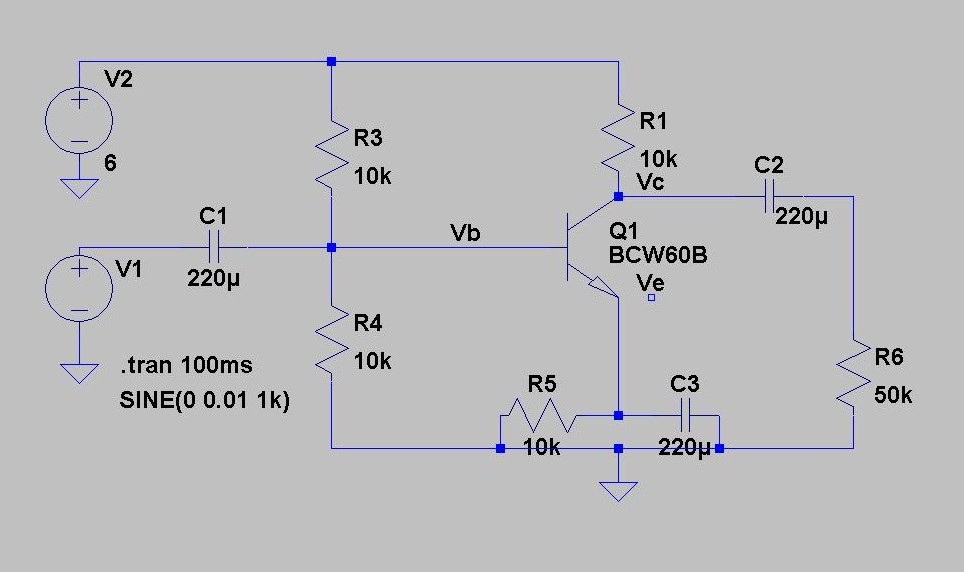
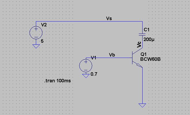
this was the circuit i used:
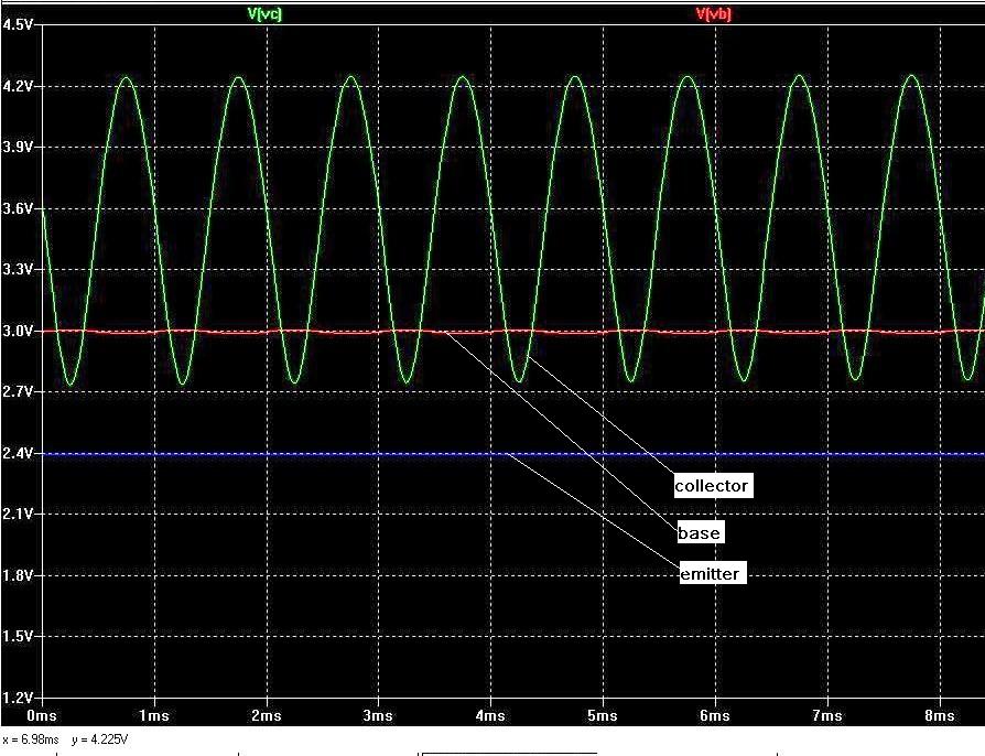
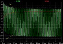
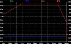
the waves looked like this:
suppose we:
take Vc to mean, voltage at collector relative to ground, and
take Vb to mean, voltage at base relative to ground, and
the condition for saturation is, when Vc < Vb, in other words, base-collector junction is forward biased.
then, when the collector curve goes below that of the base, that's when Vc is < Vb, the transistor should go into saturation, and no longer respond to signal -> constant -> flattened out at the bottom of the curve.
this will happen regardless of the fact that the lowest Vc is around 2.7V, way higher than the datasheet Vc(sat) ~= 0.2V, because saturation WILL happen when Vc < Vb. when this condition is met, saturation will happen first, then the Vc(sat) settles at around 0.2V; not the other way around, Vc reaches ~0.2V, then saturation happens and, as long as Vc is above ~0.2V, no saturation will happen.
but that's not the case, LTspice drew the whole cmoplete curve, no saturation.
i couldn't figure out why,
why LTspice is right, and
why i'm wrong.
please help me finding out where i made a mistake in my reasoning, thank you all!
i was playing with LTspice, and got the following result that i don't understand...
this was the circuit i used:
the waves looked like this:
suppose we:
take Vc to mean, voltage at collector relative to ground, and
take Vb to mean, voltage at base relative to ground, and
the condition for saturation is, when Vc < Vb, in other words, base-collector junction is forward biased.
then, when the collector curve goes below that of the base, that's when Vc is < Vb, the transistor should go into saturation, and no longer respond to signal -> constant -> flattened out at the bottom of the curve.
this will happen regardless of the fact that the lowest Vc is around 2.7V, way higher than the datasheet Vc(sat) ~= 0.2V, because saturation WILL happen when Vc < Vb. when this condition is met, saturation will happen first, then the Vc(sat) settles at around 0.2V; not the other way around, Vc reaches ~0.2V, then saturation happens and, as long as Vc is above ~0.2V, no saturation will happen.
but that's not the case, LTspice drew the whole cmoplete curve, no saturation.
i couldn't figure out why,
why LTspice is right, and
why i'm wrong.
please help me finding out where i made a mistake in my reasoning, thank you all!
Attachments
Last edited:
The collector voltage can go below the base voltage. The transistor only saturates when the collector voltage gets close to the emitter voltage.
In your case, the saturation voltage is 0.2V, but that's the voltage between collector and emitter. Normally it is abbreviated as Vce(sat), not Vc(sat). When your collector voltage drops to 2.7V, it is still 0.3V above the emitter voltage, so no saturation. If you increase the input signal a little, you will see the saturation.
In your case, the saturation voltage is 0.2V, but that's the voltage between collector and emitter. Normally it is abbreviated as Vce(sat), not Vc(sat). When your collector voltage drops to 2.7V, it is still 0.3V above the emitter voltage, so no saturation. If you increase the input signal a little, you will see the saturation.
There are a couple of current LT spice Threads running.
Yeah it would be nice if there is "Any Questions Regarding To LTSpice" thread dedicated to ANYONE who wants to ask questions.
Vce(sat) is specified at carefully controlled conditions. The NXP data sheet specifies Vce(sat) at Ic 10mA, Ib 0.25mA and Ic 50mA, Ib 1.25mA. The transistor is running less than 1mA in your simulation.
When I worked at a semiconductor company they had a trick question to ask prospective engineers. A grounded emitter transistor has only a capacitor conected between the collector and 5V. What voltage will the capacitor charge up to when the transistor is biased on? 5V - Vce(sat)? Wrong! The answer is 5V. As current falls to zero, Vce falls to zero.
When I worked at a semiconductor company they had a trick question to ask prospective engineers. A grounded emitter transistor has only a capacitor conected between the collector and 5V. What voltage will the capacitor charge up to when the transistor is biased on? 5V - Vce(sat)? Wrong! The answer is 5V. As current falls to zero, Vce falls to zero.
When I worked at a semiconductor company they had a trick question to ask prospective engineers. A grounded emitter transistor has only a capacitor conected between the collector and 5V. What voltage will the capacitor charge up to when the transistor is biased on? 5V - Vce(sat)? Wrong! The answer is 5V. As current falls to zero, Vce falls to zero.
Interesting question. I haven't tried it (I might
") ) but my instant thought is that the answer is incomplete. I don't think I'd initially trust LTspice for that either (for no good reason).
) but my instant thought is that the answer is incomplete. I don't think I'd initially trust LTspice for that either (for no good reason)." As current falls to zero, Vce falls to zero
The current will fall to zero no matter what the collector volts is. If the collector is at 3 volts the current still falls to zero. If you measure using any "normal" meter then that will also provide a current path to charge the cap and consequently bring the voltage "to zero". So you would need a VOM or FET type meter.
I don't know the answer... just thinking aloud.
Zero as 0.00 volts. I'll think about that
The collector voltage can go below the base voltage. The transistor only saturates when the collector voltage gets close to the emitter voltage.
In your case, the saturation voltage is 0.2V, but that's the voltage between collector and emitter. Normally it is abbreviated as Vce(sat), not Vc(sat). When your collector voltage drops to 2.7V, it is still 0.3V above the emitter voltage, so no saturation. If you increase the input signal a little, you will see the saturation.
thank you godfrey, i got your point!
you are saying having base-collector forward biased is merely a necessary conditon for saturation, but not a sufficient one. every book i read talks about the three operating modes, and all emphasis is on the "base-collector forward biased" condition. Vce is played down, and only mentiioned as an "oh by the way".
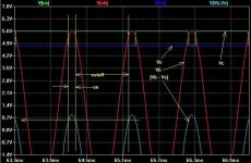
anyways, following your suggestion, i tried it out again with a 5V input signal.
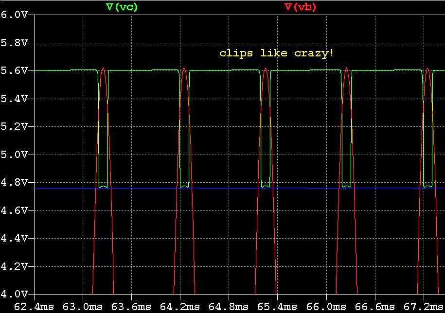
it clipped like crasy
. 5V, just to get the whole collector curve in the picture.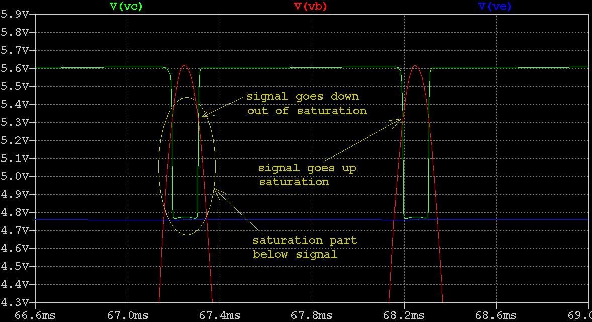
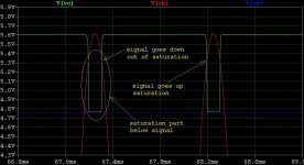
in this picture, the transistor climbed out of saturation when the signal decreased to below Vc and. it went into saturation when the signal increased to above Vc, but then saturation will not necessarily happen, only when the signal kept increasing to where Vc would decrease to where Vce~=0.2V, will saturation be realized. so the saturation determining condition is really just Vce~=0.2V, and the base-collector forward biased condition is only getting the transistor heading that way with no guarantee of saturation. the Vce(sat) notation makes sense now. did i get it right this time?
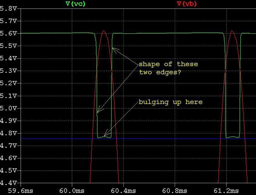
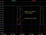
now, there is no abrupt transistion from normal operating mode to saturation mode, correct? if so, the two edges in this picture should still be part of the output sine wave, instead of abrupt theoretical straight vertical lines, correct?
also, the bottome edge of the output wave form has an upward bulging to it. it is in phase with the signal, so it can't the transistor is still trying to amplify. why the bulge, the transistor is in saturation there, it shouldn't have any response to the signal, what is it doing there?
Attachments
I don't know the answer... just thinking aloud.
Zero as 0.00 volts. I'll think about that
I've just done a quick Spice file and it seems to show the collector volts as settling at around 17mv or so. The value depends on base current and transistor. That's kind of what I would have expected tbh although I would have guessed at Vc being a little higher than spice shows.
I'm a novie with spice and it took me a while to figure out how to get the results I was expecting. Had to set various delays in the supply voltage and bias but it works OK doing that.
Attachments
There are a couple of current LT spice Threads running.
i did a search before posting. many threads posted in several forums showed up, each having to do with LTspice in its own way, not really relating to my questions. so i tarted a new one.
should i reply to existing threads, even when my questions are not exactly what the thread subject is about?
anyway, please move or delete this thread if necessary.
Vce(sat) is specified at carefully controlled conditions. The NXP data sheet specifies Vce(sat) at Ic 10mA, Ib 0.25mA and Ic 50mA, Ib 1.25mA. The transistor is running less than 1mA in your simulation.
point weill taken Loudthud. i'm just trying to understand saturation, mainly what is the mechanism of saturation, what the determining factor(s) of saturation is(are), etc.. variations in Vce(sat) under different conditions are nice to know about, thank you for that, but i'm not there yet, i need to understand the "inner workings" of saturation first.
When I worked at a semiconductor company they had a trick question to ask prospective engineers. A grounded emitter transistor has only a capacitor conected between the collector and 5V. What voltage will the capacitor charge up to when the transistor is biased on? 5V - Vce(sat)? Wrong! The answer is 5V. As current falls to zero, Vce falls to zero.
as a newbie, i don't know
. the emitter is connected to ground, collector to 5V with a cap in between. when it's on, collector and emitter are conducting; without an input signal, no Ic then, no load resistor either; so 5V. if we take quiescent current into account, maybe there will be a little voltage drop across collector-emitter(?), then 5V minus a little something. if the transistor is on means it is in normal operating mode, not in saturation mode, plus there is no signal, so nothng will drive it into satuation, then saturation doesn't come into the picture, what is the - Vce(sat) about? i really don't know, so i don't get the job huh.Rather than looking at Vb and Ve, plot the difference between them i.e. Vbe = Vb - Ve
could you teach me how to do that in LTspice, thank you ingenieus!
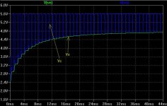
here is a picure showing Vb and Ve.
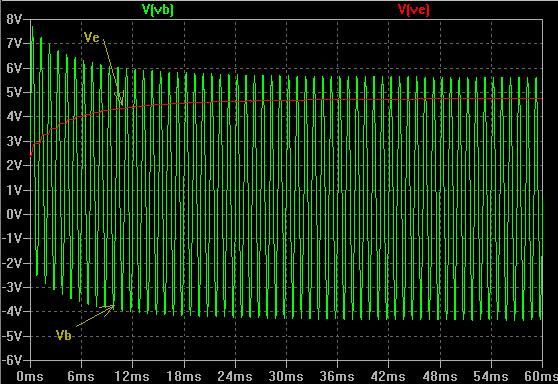
i don't know why the waves "ramp up and down" at the beginning, but after a while they become stable. so Vb constantly goes below Ve, i.e. the transistor is being constantly switched on and off, correct? how does this relate to saturation?
or, could you mean Vce = Vc - Ve?
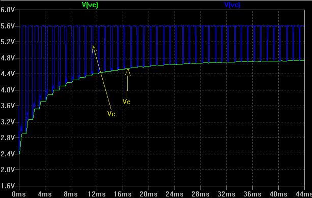
guess the difference between them should be a constant Vce(sat) ~= 0.2V?
and Ve seems to be acting as a boundary for Vc, i.e. Vc can't go below Ve, and that is saturation. furthermore, for this boundary to realize itself, Vc needs to be heading in that direction first, meaning Vbc has to get forward biased first, plus Vb has to keep going up, so Ve will come down far enough to reach this boundary for saturation to happen. is that the point?
wow, be the answer yes or not, this is a very powerful visual illustration of a device characteristics Vce(sat), in terms of device physics, plus a mechanism of how that might happen in reality. don't know whether i got this correctly or not, thank you very much ingenieus anyway!
Attachments
Last edited:
To plot V(vb) and V(ve) difference you can:
1) Right click on any one of the two nodes and select "mark as reference". Another click on the second node will give the difference.
2) Right click on the chart tittle such as "V(vb)" or "V(ve)" and you can write/type in your formula such as "V(vb)-V(ve)"
1) Right click on any one of the two nodes and select "mark as reference". Another click on the second node will give the difference.
2) Right click on the chart tittle such as "V(vb)" or "V(ve)" and you can write/type in your formula such as "V(vb)-V(ve)"
To plot V(vb) and V(ve) difference you can:
1) Right click on any one of the two nodes and select "mark as reference". Another click on the second node will give the difference.
2) Right click on the chart tittle such as "V(vb)" or "V(ve)" and you can write/type in your formula such as "V(vb)-V(ve)"
thank you very much Jay! it worked!
Rather than looking at Vb and Ve, plot the difference between them i.e. Vbe = Vb - Ve
hi ingenieus, with the help from Jay, here's the Vbe = Vb - Ve plot.
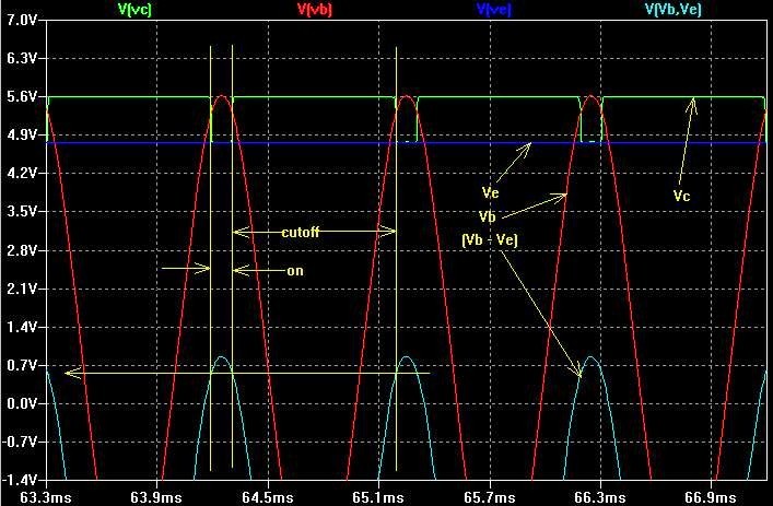
uhm... things are getting interesting!
1) saturation
looks like saturation or not is the same thing as Vbe is above ~0.7V or not, in other words, base-collector is forward biased or not. still, only that is not enough for saturation, right? Vbe has to keep increasing for Vc to dip down far enough to reach Vce(sat) for that to happen, and Vce(sat) is determined by device physics, correct?
2) the bulge
the bulge at the bottom of the Vc curve corresponds to the part of Vbe above ~0.7V, and that is when the transistor is on. outside the saturation regions in the plot, the transistor is cutoff, so Vc ~= 6V. within the saturation regions, the transistor is on, but in saturation. so how does it behave in saturation? Vc will be in phase with the signal, thus the bulging up? isn't it supposed not to respond to any signal swing?
Attachments
Last edited:
The Yahoo "LTspice" user's group at < http://tech.groups.yahoo.com/group/LTspice/ > can be a LOT of help for questions specific to LTspice, or SPICE simulation in general. It's not really a place to discuss circuit design details, though questions of that sort creep in with some regularity. (Especially since design errors can lead to simulation problems.)
Perhaps the weakest feature of LTspice (in my opinion) is the lack of comprehensive, well cross-referenced documentation. Several (OK, a few dozen - and in at least half a dozen languages!) third-parties have stepped in to create Users' Guides and Tutorials. Many of these appear to have been produced by teachers who use LTspice in courses at various academic levels from High School on up, so they tend to emphasize the features and capabilities useful in a particular curriculum. Even so, it's probably worth your time to sample a few of them. As I said, there are several to choose from - look for one that seems to match your personal learning style and level of previous experience. You'll find them listed under "Files" > "FAQ", and also under "Links", in the Yahoo group.
I think this is a friendly and very helpful group, but please respect the participants' time and effort when asking for help. Do at least a cursory search of the messages (about 50,000 of them!). There are EXCELLENT tables-of-contents for everything on the site under "Files" > "Tables of Contents". Use your web browser's "Find" feature to look for keywords in the Table of Contents files, and they will point you toward relevant discussion threads. You can effectively camoflage a dumb question if you prepend it with something like, "In message xxx it says, "{something}" but when I tried this {I got this result}."
Dale
I've just done a quick Spice file and it seems to show the collector volts as settling at around 17mv or so. The value depends on base current and transistor. That's kind of what I would have expected tbh although I would have guessed at Vc being a little higher than spice shows.
I'm a novie with spice and it took me a while to figure out how to get the results I was expecting. Had to set various delays in the supply voltage and bias but it works OK doing that.
very interesting Mooly!
i did a similar run, and got a very low collector voltage, about 6 mV.
is this due to the quiescent current?

also, the collector voltage is low, then the voltage across the cap is large. if we ignore the rather small collector voltage, that across the cap will be 5V, correct?
Attachments
Some of us find most anything to do with circuits as "interesting". By understanding how a small piece of the universe works, we can control it and use it to build cool stuff.uhm... things are getting interesting!
Well, that's definitely not incorrect, but I think it's more accurate to say that Vce(sat) is determined by the way device physics interacts with the external conditions applied to the transistor.1) saturation . . . . Vce(sat) is determined by device physics, correct?
As somebody pointed out, the BCW60 Data Sheet value for "Vce(sat)" is measured under some specific conditions, and the circuit in Post #1 is quite a ways from satisfying those conditions. Try running your simulation with the collector resistance (R1) and emitter resistance (R5) reduced to, say, 500 ohms or even 200 ohms and see if you come to the same conclusion.
(Some wise guy may suggest you do this by parameterizing the resistor values and using an LTspice ".step" directive. That's an impressive way to present results, but a lesson for another day.)
And, the Data Sheet indicates a pretty wide possible spread for Vce(sat). You probably don't know whether your SPICE model is trying to reflect the minimum, maximum, or nominal value. Since this particular transistor isn't specifically intended for switching applications, the model's author may not have tried very hard to accurately model the device's saturation behavior.
(In my experience, NXP (nee Philips) writes rather complete Data Sheets and publishes accurate SPICE models, but EVERY model, electrical or otherwise, has constraints and limitations. If it modeled EVERY aspect of the thing being represented, it would BE the thing represented.)
Transistor "saturation" seems to be a loosely defined term. I have a textbook in my hand ("Electronic Devices and Circuit Theory"; Boylestad and Nashelsky) that defines "saturation" based on two criteria:
- There is forward-biased base current greater than the base cutoff current; and
- The collector voltage is between the base voltage and emitter voltage. That is, |Vce| < |Vbe|. (Magnitude symbols " | | " used here to avoid polarity sign confusion when considering either NPN or PNP devices.)
- |Vce| <= |Vce(sat)|
- Collector voltage is well inside the base-emitter voltage, perhaps by 0.2V or 0.3V - i.e., |Vce| < ( |Vbe| - 0.2 ); or
- The DC Hfe has dropped to some fraction (perhaps 50%, or even 10%) of the linear region nominal value. In other words, forcing more current into the base does not give a corresponding increase in collector current.
I think you will find that the bulge is the result of base current feeding through the forward-biased collector-base junction, and flowing through the collector circuit. Open a second plot pane in LTSpice and look at the 3 transistor currents (collector, base, and emitter). Is the bulge as pronounced if you reduce R1?2) the bulge
Dale
very interesting Mooly!
i did a similar run, and got a very low collector voltage, about 6 mV.
is this due to the quiescent current?
also, the collector voltage is low, then the voltage across the cap is large. if we ignore the rather small collector voltage, that across the cap will be 5V, correct?
A problem here is that I think you are thinking in terms of the transistor being a "voltage driven" device when in reality it's current driven... it's a subtle distinction.
The 0.7 volts Vbe bias you have is around the voltage a base emitter junction will drop when forward biased but depending on the transistor it may be enought to turn it on, enough to cause destructive base current or perhaps not enough to do anything.
So you need to inject a current rather than a voltage. Make the 0.7 volts say 10 volts and include a series resistor of say 10K. Now the base voltage will be determined by the transistor and the current (base) will always be approximately (10-vbe)/R
- Status
- This old topic is closed. If you want to reopen this topic, contact a moderator using the "Report Post" button.
- Home
- Amplifiers
- Solid State
- LTspice / newbie question