Adcom GFA-555 mkII setting problems (solved)
Hi,
I have make a total remake of an old Adcom GFA-555 mkII with some upgrade.
I have changed:
all final BJT with MJ21193/4
drivers Q202/302 with NJW3281/1302
drivers Q201/301 with MJE15034/35
predrivers Q105/107 with MJE15035
predriver Q108 with MJE15034
trimmer with multiturn 2K
all other components are the same.
The same for other channel.
Now I have some trouble:
1) The distortion alert LED of channel R in permanently on
2) I have tried to set BIAS for channel R and I have 10mV but the predrivers run very hot.
3) I have tried to set BIAS for channel L but I have no voltage read, if I turn the trimmer I have no changes.
This is results of my measurement:
a) The output DC on speaker out is near 0,04mV on both channel.
b) Voltage referred to ground of collector of
c) Voltage across
d) Voltage on IC 101
e) Voltage on IC 151
Any suggestions ?
Hi,
I have make a total remake of an old Adcom GFA-555 mkII with some upgrade.
I have changed:
all final BJT with MJ21193/4
drivers Q202/302 with NJW3281/1302
drivers Q201/301 with MJE15034/35
predrivers Q105/107 with MJE15035
predriver Q108 with MJE15034
trimmer with multiturn 2K
all other components are the same.
The same for other channel.
Now I have some trouble:
1) The distortion alert LED of channel R in permanently on
2) I have tried to set BIAS for channel R and I have 10mV but the predrivers run very hot.
3) I have tried to set BIAS for channel L but I have no voltage read, if I turn the trimmer I have no changes.
This is results of my measurement:
a) The output DC on speaker out is near 0,04mV on both channel.
b) Voltage referred to ground of collector of
Q103: -87V,
Q108: -12,16V
Q153: -87V,
Q158: -1,7V,
Q108: -12,16V
Q153: -87V,
Q158: -1,7V,
c) Voltage across
R114: -0,82V
R115: -0,04V
R164: -0,81V
R165: -1,35V
R115: -0,04V
R164: -0,81V
R165: -1,35V
d) Voltage on IC 101
PIN 7: 19,79V
PIN 6: 3,9
PIN 6: 3,9
e) Voltage on IC 151
PIN 7: 19,79V
PIN 6: 3,6
PIN 6: 3,6
Any suggestions ?
Last edited:
Your amp is toast, or the current gain(hFE) of the new transistors is so different, the bias circuit is too narrow to allow a big enough change to bias one channel.
The constant on dist indicator suggests this circuit is broken, or the amp is oscillating wildly, producing square waves, an o-scope is needed.
Without the schematic, theres not much you can do.
The constant on dist indicator suggests this circuit is broken, or the amp is oscillating wildly, producing square waves, an o-scope is needed.
Without the schematic, theres not much you can do.
I have tested all components and are all good.
Now I did some tests on right channel input stage:
I have this result (the measure are not very accurate because of increasing temperature of transistors).
Now I did some tests on right channel input stage:
- I have disconnected IC 151
- I have disconnected pin 7, 8 and 10
- I have dicsonnected the output stage and I have tested only right channel part of input board.
I have this result (the measure are not very accurate because of increasing temperature of transistors).
Attachments
Now I have replaced the VAS stage transistor with the originals:
Q155, Q157: 2SA1142;
Q158: 2SC2682
Now all transitors of the input stage are the original type.
I have connected the final amp stage, I have setted the bias to 10mV and I have the voltage on:
PIN 7 = -7,5V
PIN 8 = -4,1V
On the speaker out : -5,89V
I think that the problem is on the current regulation of VAS stage but I don't know where.
I have measured the voltage across some resistors:
V(R166) = 0,8V -> I(R166) = 8mA
V(R164) = 0,8V -> I(R164) = 2,6mA
V(R172) = 54V -> I(R172) = 5,4mA
V(R160) = 0,7V -> I(R160) = 5,2mA
Do you have some test points voltage/current measurements ?
Thanks.
Your amp is toast, or the current gain(hFE) of the new transistors is so different, the bias circuit is too narrow to allow a big enough change to bias one channel.
The constant on dist indicator suggests this circuit is broken, or the amp is oscillating wildly, producing square waves, an o-scope is needed.
Without the schematic, theres not much you can do.
In fact the ampli have some oscillations.
I have made some measurements with an oscilloscope.
I have disconnected R126, R129, C106 and I have shorted the input.
The oscilloscope test lead is settend on 1:10.

I have solved all the problems of this amplifier and I have made some improvements.
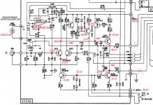
The oscillation was made by fault resistors R951, R901 in the output RC series filter.
If you you can view all my upgrades please visit my site:
Adcom GFA-555 MKII
Thanks for all.
The oscillation was made by fault resistors R951, R901 in the output RC series filter.
If you you can view all my upgrades please visit my site:
Adcom GFA-555 MKII
Thanks for all.
Thank you Antonix,
I have an old 555MkII sitting around and might well give it a try!
I powered it on a couple of evenings ago (no load) and checked a few mV DC output, so I bet it's safe enough to connect to my speakers.
You did a lot of improvements. I'll study them. Thank you,
Stefano
I have an old 555MkII sitting around and might well give it a try!
I powered it on a couple of evenings ago (no load) and checked a few mV DC output, so I bet it's safe enough to connect to my speakers.
You did a lot of improvements. I'll study them. Thank you,
Stefano
Hi Stefano,
I think that is probably only a bias setting problem.
First of all you have to check the bias settings as specified below:
1) Disconnect all input signal cables and output speaker cables.
2) Power on the amplifier and wait 20 minutes.
3) Connect a millivoltmeter across TP 201 and TP 301.
4) Adjust bias trimmer R119 to obtain a + o - 10mV on the millivoltmeter.
5) Repeat this procedures for the other channel.
Please look at the distortion leds, these must remain off.
") ).
).Hi,
please specify what you have measured,
1) DC mV on output ?
2) The distortion leds are off ?
3) The capacitors C202/C302 and C352/C252 are good ?
4) Have you verified R901 and R951 ?
In my amplifier, after all improvement that I do, the DC output I have measured is around 0,002 mV (I have matched all transistors).
The value of 9,8mV is a safe value but I think that you have to test the amplifier first with an old woofer, look at the distorsion led, listen if the sound is good for an hour, re-verify the DC output and, if is all ok, you can connect your speaker.
Hi,
I followed the instructions for bias setting according to your hints and Adcom SM. Instead of the specified 10.0mV between both TPs, I got 9.9mV on both pairs of TP.
Anyway I fear I should improve the quality of my DMM, since I can measure only one digit after the point.
DC output at binding posts is not constant (don't know if depending on my DMM accuracy or movement of the probes) but moving in a +/- 1.0 mV range.
Distortion leds are always off, capacitors seems good (any hint on testing them w/o desoldering?).
I'll check R901 and R951 and... will wire to my sub just to recheck DC output and biases between TPs.
Thanks for your help.
Stefano
- Status
- This old topic is closed. If you want to reopen this topic, contact a moderator using the "Report Post" button.
- Home
- Amplifiers
- Solid State
- Adcom GFA-555 mkII setting problems